
Ventilation control apparatus for internal combustion engine

a technology for internal combustion engines and control apparatuses, which is applied in mechanical apparatuses, combustion-air/fuel-air treatment, machines/engines, etc., can solve the problems of accelerating oil deterioration, insufficient crankcase ventilation, and internal pressure build-up of crankcases, and achieves wide supercharging range.

Inactive Publication Date: 2014-08-14
TOYOTA JIDOSHA KK
View PDF0 Cites 27 Cited by
  • Summary
  • Abstract
  • Description
  • Claims
  • Application Information

AI Technical Summary

Benefits of technology

The present invention relates to a structure for controlling the flow of blow-by gas in an internal combustion engine. The first aspect of the invention introduces the blow-by gas into the engine's bypass passage when there is a difference in pressure between the internal pressure of the exhaust sequence and the intake sequence. This allows for proper crancase ventilation even when the intake manifold pressure is positive. The second aspect the invention prevents the blow-by gas from flowing into the exhaust passage, which can occur when there is a reverse flow of gas. The third aspect allows for the connection between the PCV passage and the gas introducing means to be prohibited or allowed using a PCV valve. The fourth aspect prevents the water vapor from solidifying and blocking the gas introducing means. The fifth aspect combines the first and second aspects, allowing for ventilation through a wide range of supercharging levels. Overall, the structure of the invention provides improves engine performance and control.

Problems solved by technology

Application of the above-described blow-by gas reflux apparatus to the above-described supercharged internal combustion engine, however, poses the following problem.
Then, gas stagnates inside the crankcase, which causes a crankcase internal pressure to build up.
In the supercharged internal combustion engine, therefore, crankcase ventilation is insufficient, which may expedite deterioration of oil.

Method used


Image

  • Ventilation control apparatus for internal combustion engine
  • Ventilation control apparatus for internal combustion engine
  • Ventilation control apparatus for internal combustion engine

Examples


first embodiment

[Configuration of Ventilation Control Apparatus]

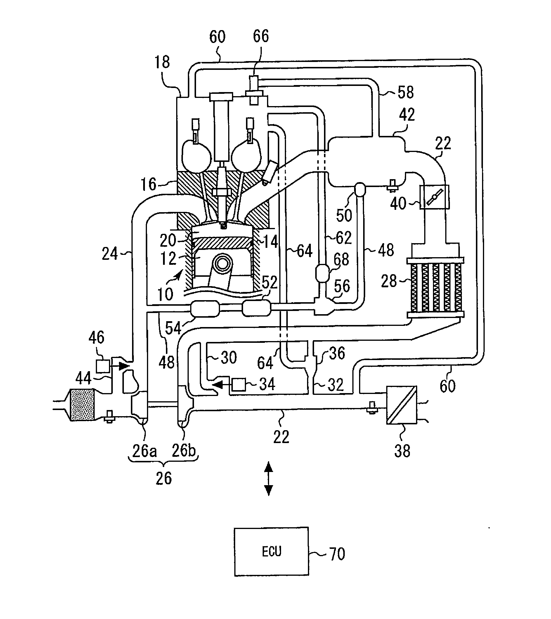
[0043]A first embodiment of the present invention will be described below with reference to FIGS. 1 to 8. FIG. 1 is an illustration showing a system configuration of a ventilation control apparatus of this embodiment. Referring to FIG. 1, the system of the embodiment includes an engine 10 as an internal combustion engine. The engine 10 may have any number of cylinders and any cylinder arrangement. The engine 10 includes a cylinder block 14 having a piston 12 thereinside. A cylinder head 16 is fitted to an upper portion of the cylinder block 14. The cylinder head 16 is covered with a cylinder head cover 18. A space from an upper surface of the piston 12 to the cylinder head 16 forms a combustion chamber 20. The cylinder head 16 has an intake passage 22 and an exhaust passage 24 that communicate with the combustion chamber 20.

[0044]The system of this embodiment further includes a supercharger 26. The supercharger 26 includes a turbine 26...

second embodiment

[Characteristics of the Second Embodiment]

[0062]A second embodiment of the present invention will be described below with reference to FIG. 9. This embodiment is characterized in that a routine shown in FIG. 9 is performed in the system configuration described with reference to the first embodiment.

[0063]In the first embodiment described above, control to close the PCV valve 68 is performed when the crankcase internal pressure decreases during the introduction of the EGR gas. This prevents occurrence of an unintended flow of gas, in which the EGR gas flows through the ejector 56 and the PCV passage 62 into the crankcase. Such an unintended flow of gas, however, occurs during not only the introduction of the EGR gas, but also performance of escape control. It is here noted that the escape control is to force the intake air in the intake passage 22 to be introduced into the exhaust passage 24 by way of the EGR passage 48 in order to enhance a supercharging response. During the perform...


PUM


Abstract

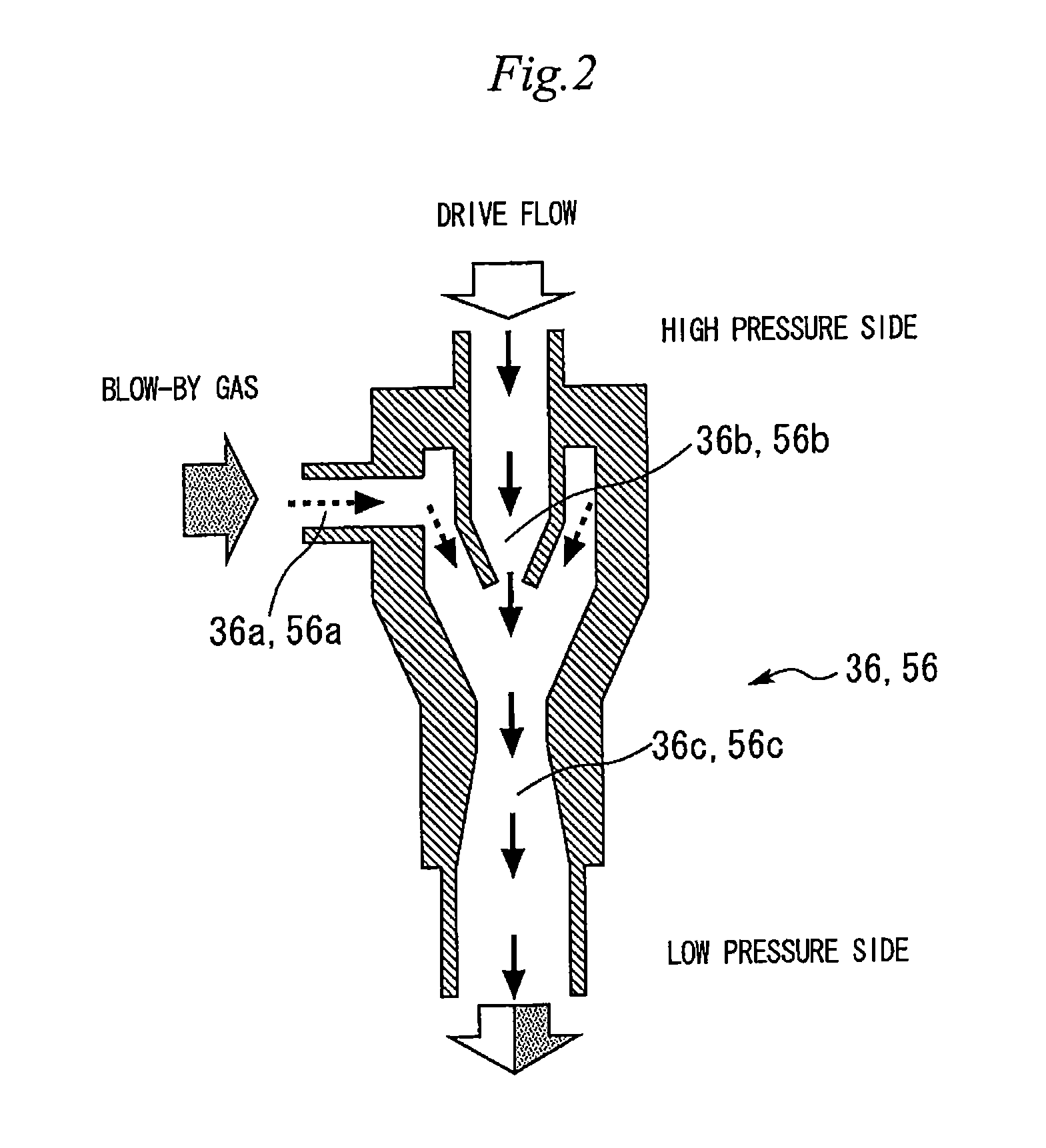
A ventilation control apparatus for a supercharged internal combustion engine that can perform crankcase ventilation favorably. A system includes a supercharging system, an EGR mechanism, and a blow-by gas reflux mechanism. The EGR mechanism includes an ejector between an EGR valve and an EGR cooler. A suction port is connected to a cylinder head cover via a PCV passage. A nozzle portion is connected to an EGR passage on the EGR cooler side. A diffuser portion is connected to the EGR passage on the EGR valve side. By making EGR gas flow through the EGR passage, gas in the crankcase can be drawn through the PCV passage to thereby be burned, together with the EGR gas or fresh air, in an engine.

Description

TECHNICAL FIELD[0001]The present invention relates, in general, to ventilation control apparatuses for internal combustion engines and, in particular, to a ventilation control apparatus for an internal combustion engine that treats blow-by gases.BACKGROUND ART[0002]A known blow-by gas reflux apparatus reintroduces to an internal combustion engine by way an intake manifold, and burns, gases that flow through a gap between a piston and a cylinder wall surface of the internal combustion engine into a crankcase without allowing the gases to be released into the atmosphere. For example, patent document 1 discloses a blow-by reflux apparatus that includes a first positive crankcase ventilation (PCV) passage connecting a cylinder head and an intake passage of the internal combustion engine, a second PCV passage connecting a portion of the intake passage downstream of a connection between the first PCV passage and the cylinder head, and a PCV valve disposed at the second PCV passage. The bl...

Claims


Application Information

Patent Timeline
Patent Type & Authority Applications(United States)
IPC IPC(8): F01M13/00
CPCF01M13/0011F02B37/18F02B37/16F02M35/10222F02B29/0406F02M25/06F02M35/10157F01M13/022F01M2013/027F02M26/05F02M26/19F02M26/28F02M26/35Y02T10/12
Inventor HOTTA, SHINTARO
Owner TOYOTA JIDOSHA KK
Learn More