Conveying chain

a technology of conveying chain and chain, which is applied in the direction of driving chain, chain elements, belt/chain/gearing, etc., can solve the problems of generating dirt accumulation, and achieve the effect of reducing the wear of the conveying chain in use, increasing the smoothness of the conveying chain operation and maximizing the use duration

Inactive Publication Date: 2014-08-07
MING CHANG TRAFFIC PARTS MFG
View PDF9 Cites 3 Cited by
  • Summary
  • Abstract
  • Description
  • Claims
  • Application Information

AI Technical Summary

Benefits of technology

The present invention provides a conveying chain with a plurality of chain sets connected together. Each chain set includes a pin member, inner plates, outer plates, and a chain bush. The chain bush has a through hole connected to an outside through openings. This design allows for the quick discharge of dust or impurities entering into the through hole, preventing their accumulation between the chain bush and the pin member. This results in a smoother chain operation and increased duration of use.

Problems solved by technology

As a result, a lubricant inside of the chain bush 113 mixes with the dust or the impurities and generates an accumulation of the dirt.

Method used


Image

  • Conveying chain
  • Conveying chain
  • Conveying chain

Examples


Embodiment Construction

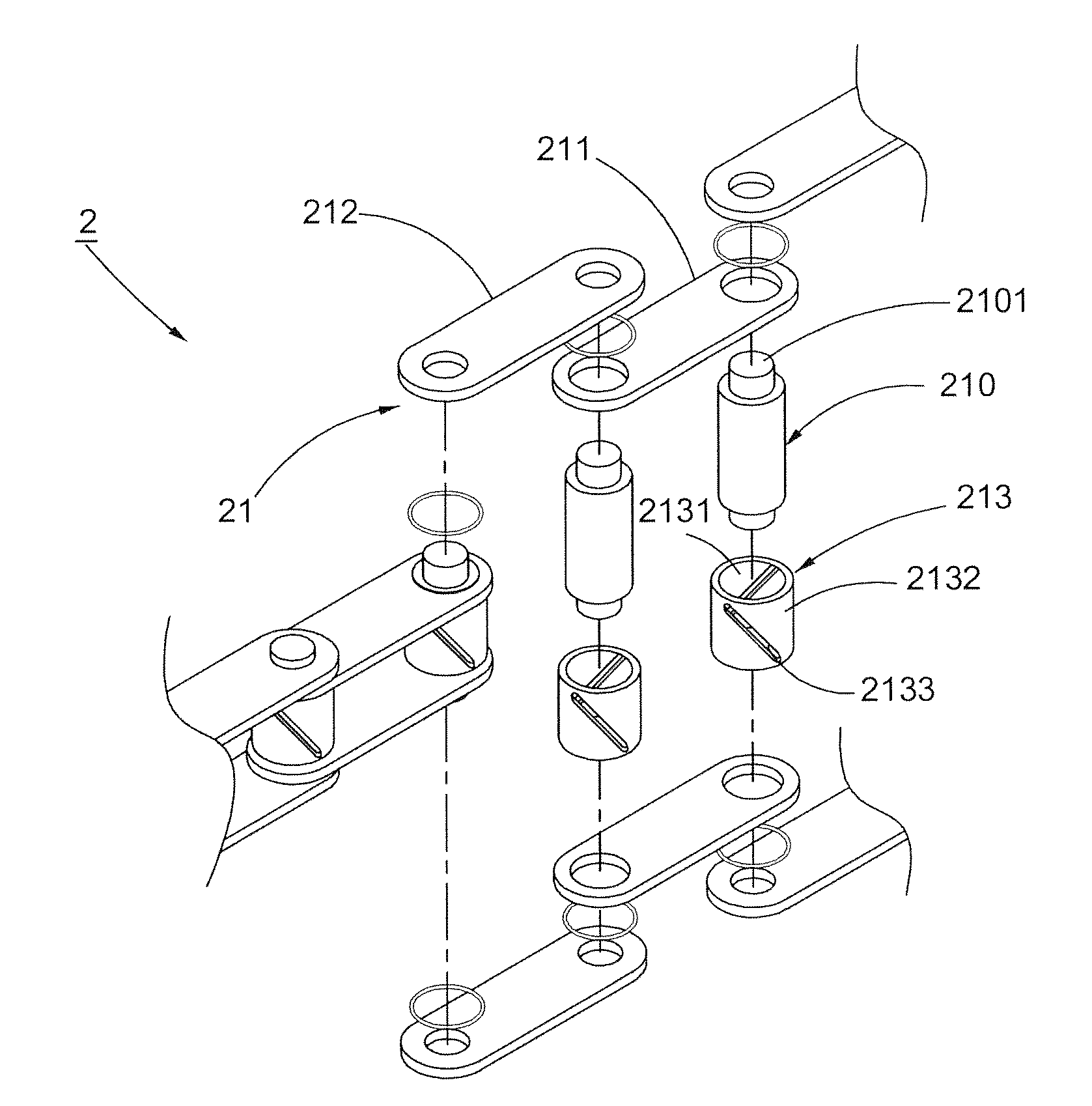
[0018]Referring to FIG. 3, a first preferred embodiment of the conveying chain 2 comprises a plurality of chain sets 21 connected together. Each chain set 21 comprises a chain bush 213, inner and outer plates 211,212 respectively disposed on both sides of the chain bush 213, and a pin member 210 penetrating the chain bush 213 and fitting with the inner and the outer plates 211,212. A through hole 2131 is formed in an inside of the chain bush 213 for allowing the pin member 210 to penetrate and fit therein. A connecting portion 2101 can be integrally protruded from the pin member 210 for allowing the inner and the outer plates 211,212 to place thereon, or alternatively, in this embodiment, the connecting portion 2101 is an independent shaft penetrating through the pin member 210, whereby the connecting portion 2101 is able to protrude from both ends of the pin member 210 respectively. A plurality of openings 2133 are defined at intervals on a circumference 2132 of the chain bush 213,...


PUM


Abstract

A conveying chain comprises a plurality of chain sets connected together, each chain set comprises a chain bush, inner plates and outer plates respectively disposed on both sides of the chain bush, and a pin member penetrating the chain bush and connecting the inner and the outer plates, wherein a plurality of openings are defined at intervals on a circumference of the chain bush. A through hole is communicated with an outside via the openings, so that dust or exterior impurities accumulated between the chain bush and the pin member can be outwardly discharged through the openings to prevent the accumulation of the dust or impurities from having an adverse influence on the transmission of the chain and to increase the smoothness of the chain operation and the use duration efficiently.

Description

BACKGROUND OF THE INVENTION[0001]1. Field of the Invention[0002]The present invention relates to a chain design, particularly to a conveying chain.[0003]2. Description of the Related Art[0004]Nowadays, transmission works of a variety of machinery apparatus are mostly driven with chains. Referring to FIG. 1, the conventional chain 1 comprises a plurality of chain sets 11 connected together, each chain set 11 comprises a pin member 110, inner plates 111, outer plates 112, and a chain bush 113. Wherein, a hole 1131 is formed in an inside of the chain bush 113, and a connecting portion 1101 is protruded outwards from both ends of the pin member 110 for allowing the inner plates 111 and the outer plates 112 to fit thereon. Therefore, the chain 1 achieves an effect of transmission or conveyance, which accordingly facilitates a generated force to be smoothly transmitted, or an object to be conveyed easily.[0005]However, after using, referring to FIG. 2, the chain bush 113 is penetrated by ...

Claims


Application Information

Patent Timeline
IPC IPC(8): B65G15/48
CPCB65G15/48B65G17/38F16G13/06F16G13/18
Inventor HUANG, YI-CHENG
Owner MING CHANG TRAFFIC PARTS MFG
Why Eureka
Try Eureka