
Drillship having vortex suppresion block with recessed flow stabilizing section in moon pool

a technology of vortex suppression and stabilizing section, which is applied in the field of drillships with vortex suppression blocks with recessed flow stabilizing sections in moon pools, can solve the problems of degrading disturbing a free surface, and low economical efficiency, so as to improve the resistance performance of the drillship, reduce the flow introduced, and reduce the pressure variability

Active Publication Date: 2014-07-24
HYUNDAI HEAVY IND CO LTD
View PDF3 Cites 11 Cited by
  • Summary
  • Abstract
  • Description
  • Claims
  • Application Information

AI Technical Summary

Benefits of technology

The present invention controls the flow and vortex at the edge of the bow side of the drillship to reduce pressure variability caused by the collision of streamlines and vortex at the stern side. This improves the resistance performance of the drillship, reduces the flow introduced from the stern into the moon pool, and stabilizes the free surface in the moon pool. Additionally, the bottom of the vortex suppression block is recessed in an upward direction, which improves the economics of shipbuilding. These technical effects make the invention ideal for industrial applications.

Problems solved by technology

With the development of industries all over the world, the use of petroleum and a natural gas has increased, and thus concern for the development of minor marginal oil fields or deepwater oil fields, which have been ignored because of low economical efficiency, has been rising.
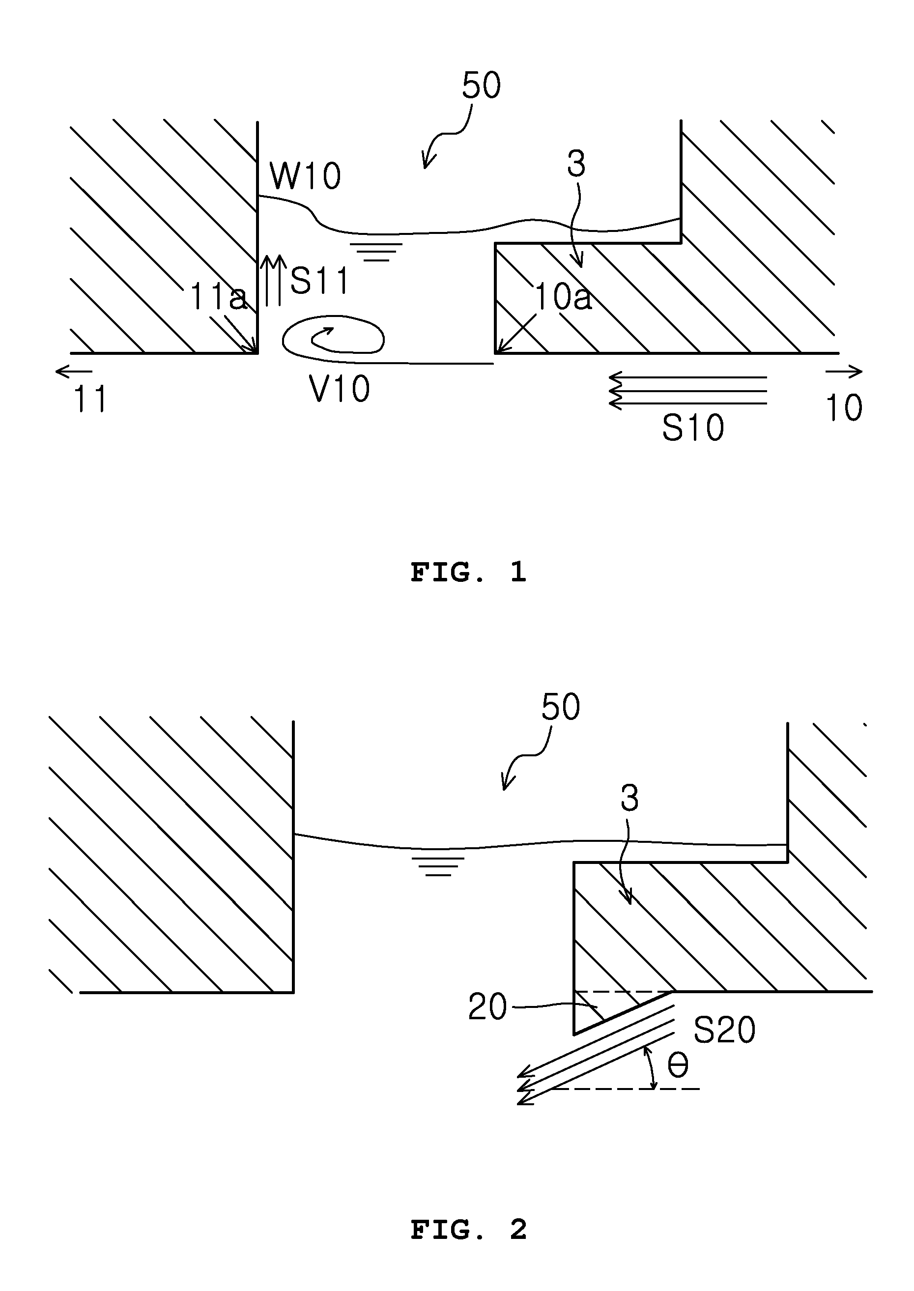
The turbulent flow makes the free surface unstable, and increases a time variation in resistance, thereby degrading the resistance performance of the drillship.
In addition, there is a problem in that a part S11 of the flow is introduced into the moon pool 50 by the vortex colliding with the edge located on the stern side, thereby disturbing a free surface W10 in the moon pool 50.
However, in the turbulent flow reducing structure described above, there are problems as follows.
Further, the inclined protrusion 20 becomes too large when attempting performance improvement while keeping the separation angle constant.
However, there are disadvantages in that there is a reduced ability to control the flow and the vortex separated from the edge of the bow and thereby reduce pressure variability caused by collision of the streamlines and the vortex at the edge of the stern, because introduction of the external flow into the moon pool is not reduced.
Additionally, installation of moon pool plates with an excessively complex configuration creates a problem in that weight and cost are increased.
However, there are disadvantages in that there is a reduced ability to control the flow and the vortex separated from the edge of the bow and thus reduce pressure variability caused by collision of the streamlines and the vortex at the edge of the stern, because introduction of the external flow into the moon pool is not reduced, and a problem in that an increase in weight and an increase in manufacturing cost of the drillship occur due to installation of the seawater flow change structure that is horizontally disposed along the vertical wall with an excessively complex configuration.
Most of them have a disadvantage in that there is a reduced ability to control the flow and the vortex separated from the edge of the bow and thus reduce the pressure variability caused by the collision of the streamlines and the vortex at the edge of the stern, because introduction of the external flow into the moon pool is not reduced, and a problem in that an increase in weight and an increase in manufacturing cost of the drillship occur due to addition of an additional complex apparatus configuration in the moon pool.

Method used


Image

  • Drillship having vortex suppresion block with recessed flow stabilizing section in moon pool
  • Drillship having vortex suppresion block with recessed flow stabilizing section in moon pool
  • Drillship having vortex suppresion block with recessed flow stabilizing section in moon pool

Examples


Embodiment Construction

[0042]Hereinafter, configurations and functions of embodiments of the present invention will be described in detail with reference to the accompanying drawings. Furthermore, in the following description of the present invention, details of well-known functions and structures incorporated herein may be omitted to avoid unnecessarily obscuring the subject matter of the present invention.

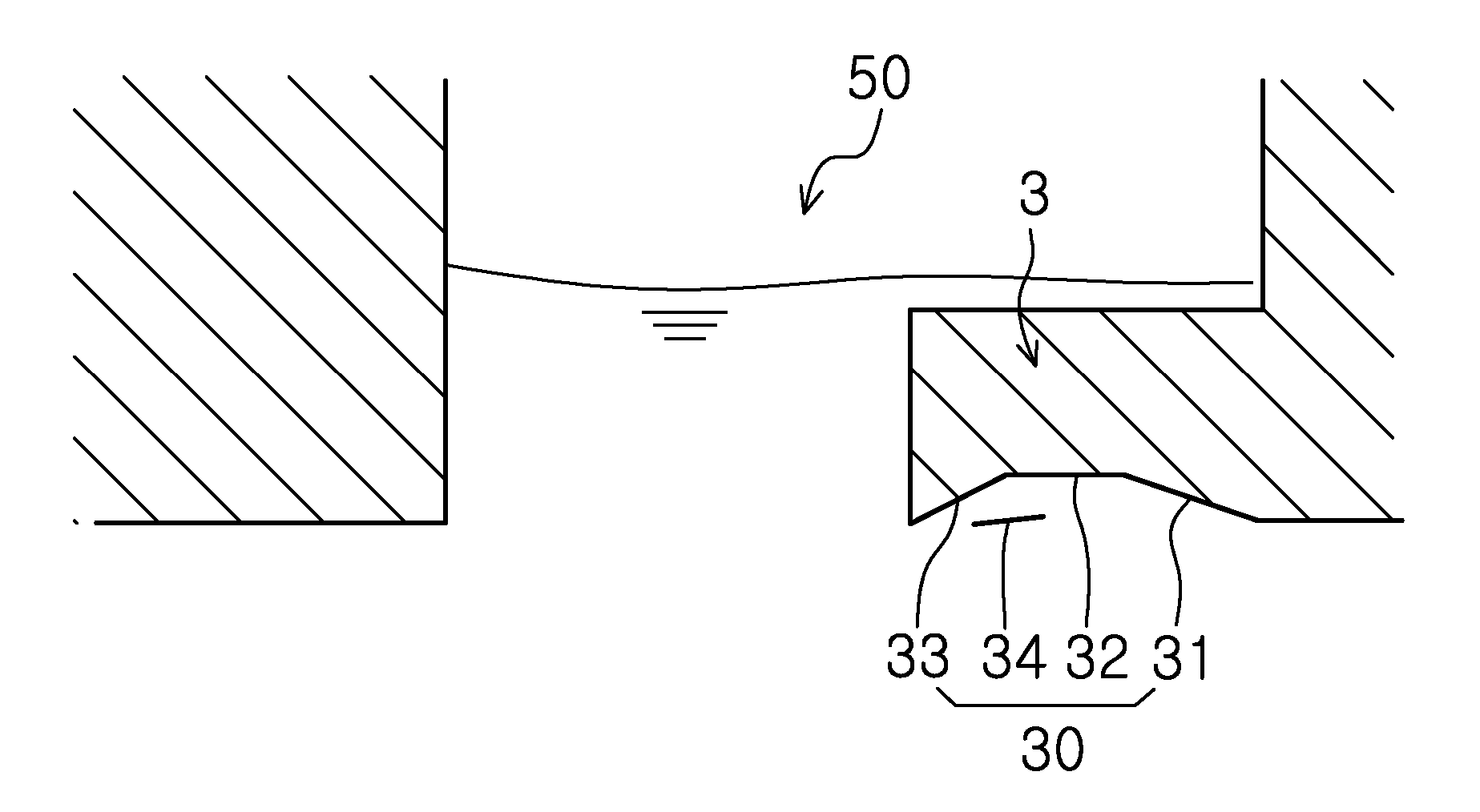
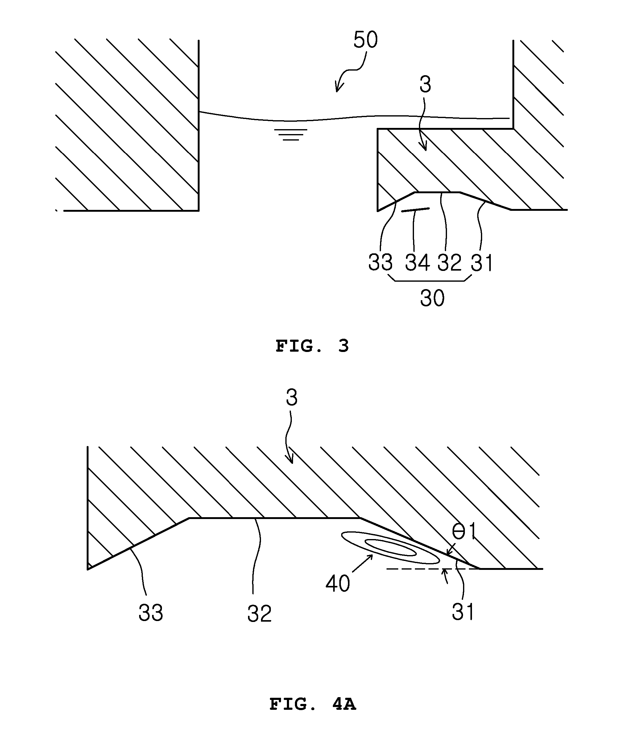
[0043]FIG. 3 is a side view of a moon pool that includes a flow stabilizing section according to one embodiment of the present invention. As shown in FIG. 3, to suppress a vortex generated by an external flow S10 introduced into a moon pool 50 that is vertically formed in the hull of the drillship, a vortex suppression block 3 protrudes from a bow side toward a stern side of the bottom of the moon pool, and a recessed flow stabilizing section 30 is formed by recessing the bottom of the vortex suppression block 3 toward an upper portion of the hull.

[0044]The recessed flow stabilizing section 30 that is ...


PUM


Abstract

Disclosed is a drillship having a vortex suppression block with a recessed flow stabilizing part in a moon pool. The flow stabilizing section is formed so that a bottom of the vortex suppression block that protrudes from a bottom of a hull toward a stern in the moon pool is recessed in an upward direction of the hull to stabilize a flow in the moon pool and reduce a variation in resistance of the drillship. The flow stabilizing section (30) is formed by partly recessing the bottom of the vortex suppression block toward an upper portion of the hull. The drillship having this configuration provides resistance performance improvement and flow stabilization of the drillship.

Description

TECHNICAL FIELD[0001]The present invention relates, in general, to, a drillship having a vortex suppression block with a recessed flow stabilizing section in a moon pool installed in the bottom of the hull, and more particularly, to a drillship having a vortex suppression block with a recessed flow stabilizing section, in which a moon pool is subjected to a change in shape on a bow side so as to control streamlines and vortexes separated by an edge of the moon pool which is located on the bow side, thereby reducing a variation in resistance applied to the moon pool, stabilizing a free surface in the moon pool, and causing the vortex suppression block to only minimally protrude from the bottom of the hull.BACKGROUND ART[0002]With the development of industries all over the world, the use of petroleum and a natural gas has increased, and thus concern for the development of minor marginal oil fields or deepwater oil fields, which have been ignored because of low economical efficiency, h...

Claims


Application Information

Patent Timeline
Patent Type & Authority Applications(United States)
IPC IPC(8): B63B1/32B63B35/44
CPCB63B35/44B63B1/32B63B3/14B63B2003/147Y02T70/10
Inventor LEE, SANG-BONGLEE, KANG-HOONANN, YOU-WONKIM, HYUNG-KWANCHUNG, SEOK-HOCHUNG, YONG-KWANKWON, MIN-JAE
Owner HYUNDAI HEAVY IND CO LTD
Learn More