Noise suppression apparatus and control method thereof
a technology of noise suppression apparatus and control method, which is applied in the direction of transducer casing/cabinet/support, electrical transducer, instruments, etc., can solve the problems of lowering the target sound suppression performance, unable to sufficiently suppress non-directional noise such as wind noise, etc., and achieve the effect of accurate suppression of only noise from the audio signal
- Summary
- Abstract
- Description
- Claims
- Application Information
AI Technical Summary
Benefits of technology
Problems solved by technology
Method used
Image
Examples
first embodiment
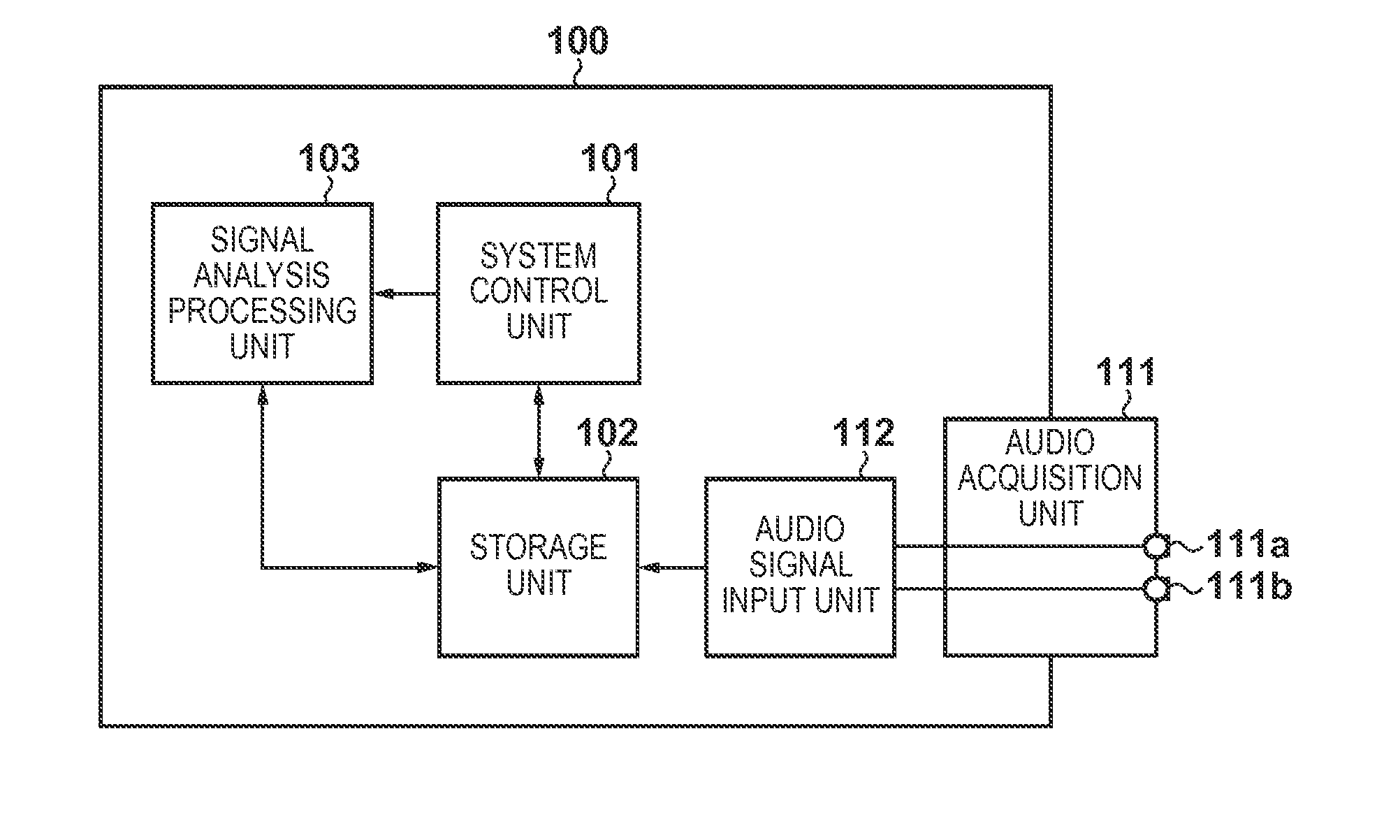
[0035]FIG. 1 is a block diagram showing an embodiment of the present invention. In a noise suppression apparatus shown in FIG. 1, a principal system controller 100 includes a system control unit 101 which controls all components, a storage unit 102 which stores various data, and a signal processing unit 103 which executes signal analysis processing.
[0036]The noise suppression apparatus includes an audio acquisition unit 111 and audio signal input unit 112 as components which implement functions of an audio acquisition system. In this embodiment, the audio acquisition unit 111 is configured by a 2ch stereo microphone including two microphone elements 111a and 111b which are disposed to be spaced apart from each other. Assume that the position coefficients of the respective microphone elements are held in advance in the storage unit 102. Alternatively, the position coefficients may be externally input via a data input / output unit (not shown) which is mutually connected to the storage ...
second embodiment
[0070]In the above embodiment, whether to select an adaptive beamformer or fixed beamformer is judged for each frequency. In the following embodiment, a switching frequency of beamformers is introduced in consideration of the tendency that the power of wind noise assumed as a practical example of non-directional noise becomes stronger as a frequency is lower.
[0071]That is, in a frequency range not less than the switching frequency, the power of wind noise is smaller than a target sound, as shown in FIG. 2A, and it is considered that the adaptive beamformer automatically forms a sharp null in a target sound direction, thus selecting the adaptive beamformer. On the other hand, in a frequency range less than the switching frequency, it is considered that the power of wind noise is comparable to the target sound, and a moderate null is automatically formed by the adaptive beamformer, thus selecting the fixed beamformer, as shown in FIG. 2B.
[0072]As the switching frequency, for example, ...
third embodiment
[0081]In this embodiment, a switching frequency is determined from noise extracted by an adaptive beamformer, and noise suppression processing is executed according to the flowchart shown in FIG. 7.
[0082]Since the process of step S701 is the same as that of step S301, a description thereof will not be repeated.
[0083]Steps S702 to S705 are processes for each frequency, and are executed in a frequency loop. The processes of steps S702 to S704 are the same as those of steps S302 to S304.
[0084]In step S705, by filtering microphone signals, as given by equation (8), Fourier coefficients Y(f) of noise-extracted signals are acquired. However, since filter coefficients of a beamformer calculated at this time are wadapt only, noise extraction is executed by the adaptive beamformer alone.
[0085]In step S706, a switching frequency is determined from the Fourier coefficients of the noise-extracted signals acquired in step S705.
[0086]FIG. 8 shows a spectrogram which displays amplitude spectra obt...
PUM
 Abstract
Description
Claims
Application Information
 - R&D
- Intellectual Property
- Life Sciences
- Materials
- Tech Scout
- Unparalleled Data Quality
- Higher Quality Content
- 60% Fewer Hallucinations
Browse by: Latest US Patents, China's latest patents, Technical Efficacy Thesaurus, Application Domain, Technology Topic, Popular Technical Reports.
© 2025 PatSnap. All rights reserved.Legal|Privacy policy|Modern Slavery Act Transparency Statement|Sitemap|About US| Contact US: help@patsnap.com


