Stent Deployment Device and Methods for Use

a technology for deploying devices and stents, applied in the field of stent deployment devices and methods for use, can solve the problems of not being able to interact with stent grafts, conventional stent deployment methods and devices can only be used with stents, and not being able to use stent grafts

Inactive Publication Date: 2014-06-26
SANFORD HEALTH
View PDF4 Cites 8 Cited by
  • Summary
  • Abstract
  • Description
  • Claims
  • Application Information

AI Technical Summary

Benefits of technology

The present invention provides a stent deployment device that can deploy either a stent or a stent graft based on the ratio of stents. This device can improve stent positioning and fixation within a target lumen and may even pack the stent or stent graft in the lumen. Additionally, this device has the benefit of a stent restraint that allows for easy recapture of a partially deployed stent back into the deployment device, which can be useful in cases where the stent is not fully deployed. The invention also includes methods for use of this stent deployment device.

Problems solved by technology

Conventional stent deployment methods and devices can only be used with stents, as opposed to stent grafts.
This interaction is not possible with a stent graft because the graft covering prevents the stent restraint from locking onto the wireframe of a stent graft.

Method used


Image

  • Stent Deployment Device and Methods for Use
  • Stent Deployment Device and Methods for Use
  • Stent Deployment Device and Methods for Use

Examples


Embodiment Construction

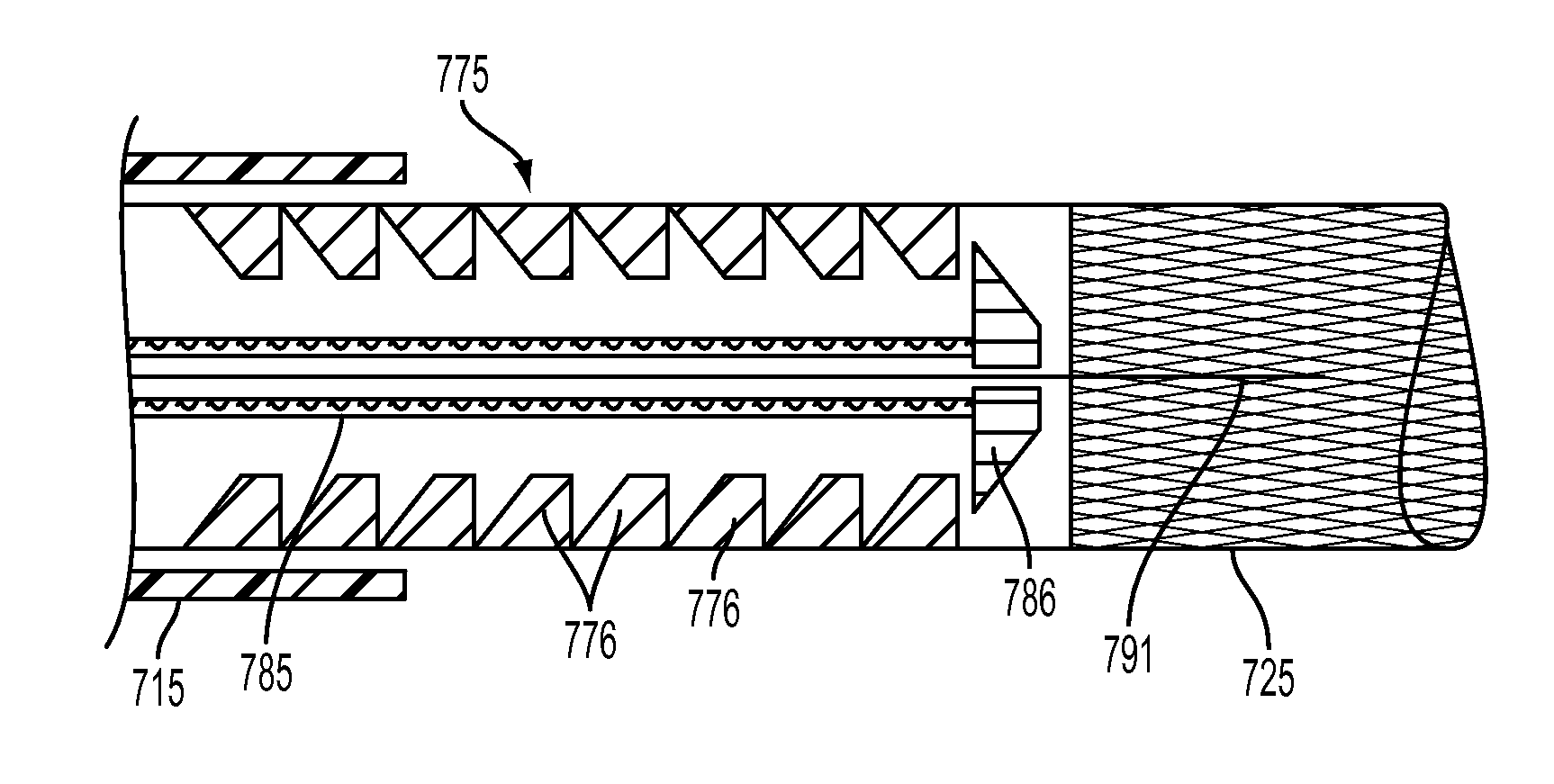
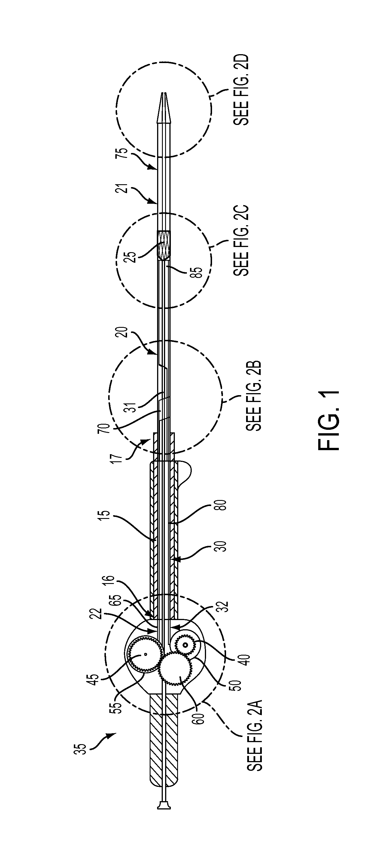
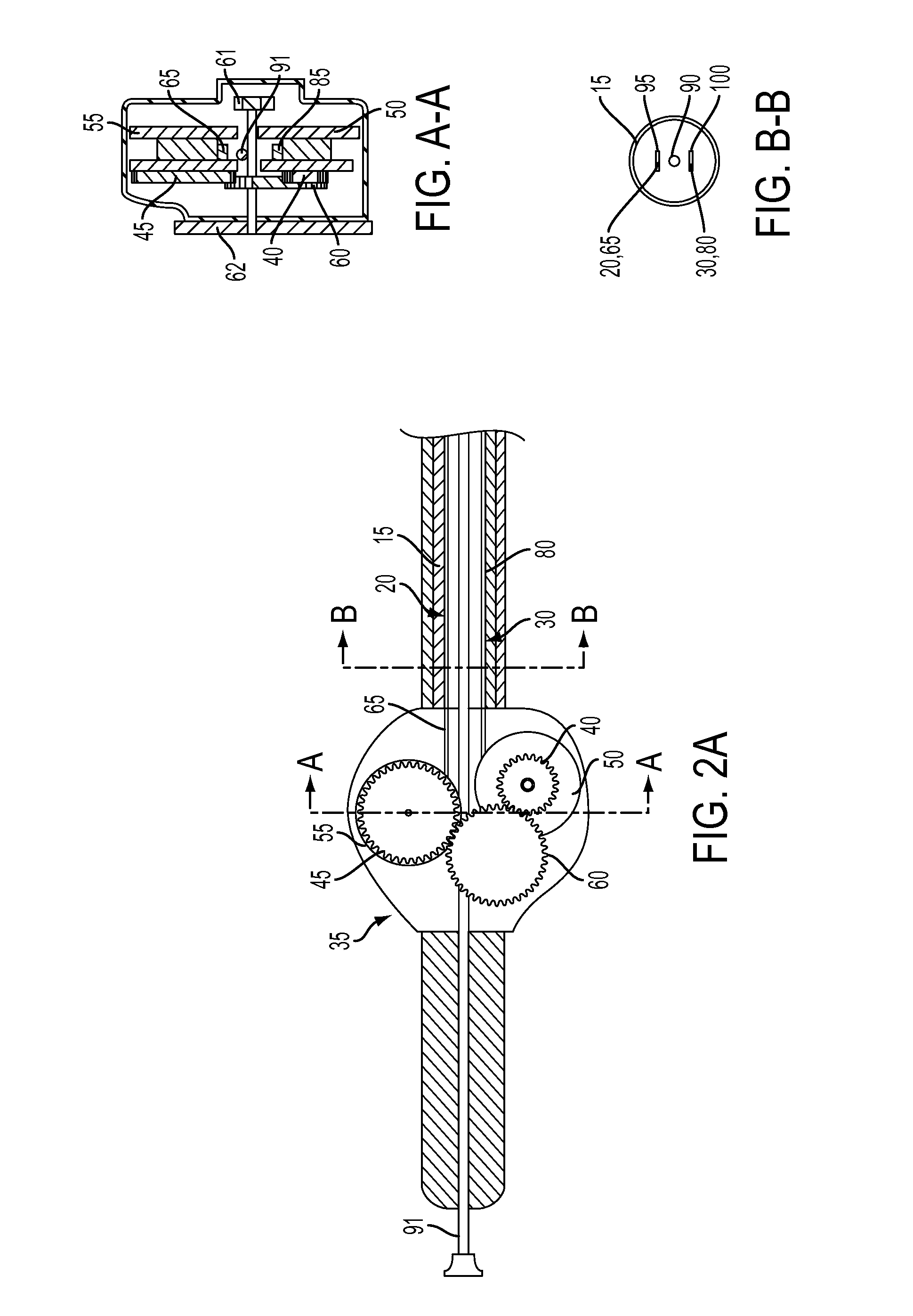
[0035]In a first aspect, as shown in FIGS. 1 and 2A-D, 4, 5A-B and 6A-B, the present invention may take the form of a stent deployment device 10 comprising: (a) an outer sheath 15, where the outer sheath 15 has a proximal end 16 and a distal end 17, (b) a pull apparatus 20 at least partially disposed within the outer sheath 15, where a portion 21 of the pull apparatus 20 is sized and shaped to receive a stent or a stent graft 25, (c) a push apparatus 30, where a portion 31 of the push apparatus 30 is sized to fit within the pull apparatus 20, and (d) a push-pull drive mechanism 35 in mechanical communication with the pull apparatus 20 and the push apparatus 30, where the push-pull drive mechanism 35 includes at least a push gear 40 and a pull gear 45 or a push reel 50 and a pull reel 55 that are sized and shaped based on a stent ratio.

[0036]As used herein, with respect to measurements and calculations, “about” means + / −5%.

[0037]As used herein, “stent” is used broadly to refer to bot...


PUM


Abstract

A stent deployment device and methods for use, where the device comprises: (a) an outer sheath having a proximal end and a distal end, (b) a pull apparatus at least partially disposed within the outer sheath, where a portion of the pull apparatus is sized and shaped to receive a stent or a stent graft, (c) a push apparatus, where a portion of the push apparatus is sized to fit within a portion of the pull apparatus, and (d) a push-pull drive mechanism in mechanical communication with the pull and push apparatuses, where the push-pull drive mechanism includes at least a push and a pull gear or a push and a pull reel sized and shaped based on a stent ratio.

Description

RELATED APPLICATIONS[0001]This application is a continuation application of and claims priority to U.S. Non-Provisional application Ser. No. 13 / 943,863 entitled “Stent Deployment Device and Methods for Use,” filed Jul. 17, 2013, which in turn claims priority to U.S. Provisional Application No. 61 / 740,161 entitled “Stent Deployment Device,” filed Dec. 20, 2012 and to U.S. Provisional Application No. 61 / 834,014 entitled “Stent Deployment Device,” filed Jun. 12, 2013, which are hereby incorporated by reference in their entirety.BACKGROUND OF THE INVENTION[0002]Stent deployment devices are utilized to direct the placement of a stent in a human or animal body and to ultimately eject and deploy a stent in a targeted lumen. Conventional stent deployment methods and devices can only be used with stents, as opposed to stent grafts. This is because known stent restraint mechanisms that prevent premature deployment must physically interact with the stent wires. This interaction is not possible...

Claims


Application Information

Patent Timeline
Patent Type & Authority Applications(United States)
IPC IPC(8): A61F2/966
CPCA61F2/966A61F2002/9517A61F2/9517
Inventor KELLY, PATRICK W.
Owner SANFORD HEALTH
Why Eureka
Try Eureka