Eureka AIR delivers breakthrough ideas for toughest innovation challenges, trusted by R&D personnel around the world.

Reducing RF energy leakage between battery and PCB

a technology of rf energy leakage and battery, applied in the direction of antenna details, antenna couplings, antennas, etc., can solve the problems of inability to ground frequently enough, high production costs of chassis and parts, and the larger the phone,

Active Publication Date: 2014-06-26
GOOGLE TECH HLDG LLC
View PDF2 Cites 10 Cited by
  • Summary
  • Abstract
  • Description
  • Claims
  • Application Information

AI Technical Summary

Benefits of technology

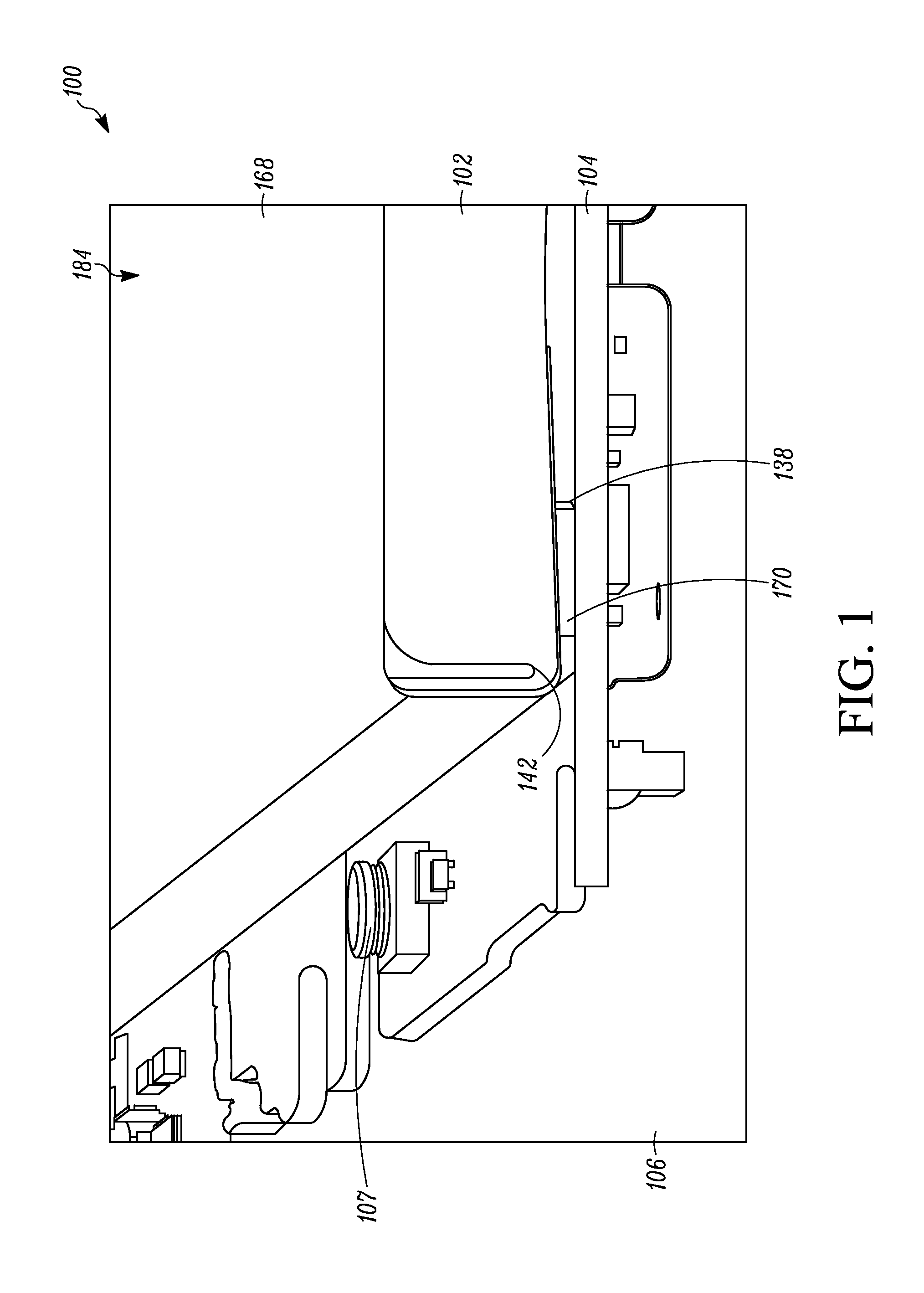
The patent is about an improved system and method for reducing RF energy leakage between the battery and PCB in electronic communication devices. The system uses a conductive metal, such as aluminum foil, to wrap the edges of the battery and provide electrical connectivity to the PCB. A conductive spacer can be used to make electrical contact between the foil and battery ground. The system reduces RF energy trapped between the battery and PCB, minimizing cavity resonances and improving performance and efficiency of the device. The method is cost-effective, space-saving, and easy to manufacture and use.

Problems solved by technology

This can cause the older phones to be larger.
Furthermore, such chassis and parts are expensive to produce and additional spring contacts are often required for grounding.
Moreover, the metal chassis is not always able to ground frequently enough to provide solid battery isolation due to screw bosses and other mechanical limitations.
Also, the metal chassis takes away additional space from the antenna volume.
If the battery is not well isolated, RF energy from antennas can get caught between the battery and PCB.
This causes cavity resonances at undesired frequencies, often in the bands of interest, which degrades antenna performance and performance of the electronic communications device.

Method used


Image

  • Reducing RF energy leakage between battery and PCB
  • Reducing RF energy leakage between battery and PCB
  • Reducing RF energy leakage between battery and PCB

Examples


Embodiment Construction

[0017]An improved system and method of reducing radio frequency (RF) energy leakage between a battery and printed circuit board (PCB) is provided, which is effective, economical, attractive and easy to manufacture and use. The improved system and method of reducing RF energy leakage between the battery and PCB also reduces cost, space, and encroachment into antenna volume area. Advantageously, in the improved system and method, there is little or no RF energy trapped between the battery and PCB and there are minimal or no undesired cavity resonances. Furthermore, the improved system and method provides enhanced performance and better efficiency of the electronic communications device.

[0018]The improved system and method of reducing RF energy leakage can use a conductive metal, such as aluminum foil, to wrap the edges of the battery. Electrical connectivity can be provided by metal conductors or battery foil, such as: metallic foil, strips, rails, tapes, or other conductors on the ba...


PUM


Abstract

An improved system 100 and method of reducing RF energy leakage from being trapped in a gap (cavity) 178 between a battery 102 and printed circuit board (PCB) 104 in an electronic communications device 106 is provided by a RF shield assembly that can extend between the battery and the PCB. The RF shield assembly can comprise a conductive wrap 168 and conductive foam 170 connected to metal pads 138 and 140 along the ground plane 136 of the PCB 104.

Description

BACKGROUND OF THE INVENTION[0001]1. Field of the Disclosure[0002]The disclosure relates in general to electronic communications devices and more particularly to an electronic communications device, such as a mobile phone, with an antenna positioned near a battery such that radio frequency (RF) energy is trapped between the battery and a printed circuit board (PCB) in the electronic communications device.[0003]2. Background Art[0004]In older electronic devices, such as conventional mobile phones like KRAZR, PEBL, Droid Razr and others, the battery sits inside a grounded, metal “bath tub” or a grounded metal chassis which required extra space. This can cause the older phones to be larger. Furthermore, such chassis and parts are expensive to produce and additional spring contacts are often required for grounding. Moreover, the metal chassis is not always able to ground frequently enough to provide solid battery isolation due to screw bosses and other mechanical limitations. Also, the m...

Claims


Application Information

Patent Timeline
Patent Type & Authority Applications(United States)
IPC IPC(8): H01Q1/52
CPCH01Q1/526H01Q1/243H04M1/0262H04M1/0277
Inventor COLES, KATHERINE H.ASRANI, VIJAY L.VOGEL, DAVID R.
Owner GOOGLE TECH HLDG LLC
Why Eureka
Eureka Blog
Learn More