
Dense structure from motion

a technology of dense structure and motion, applied in the field of dense structure from motion, can solve the problem of similar structure finding problem in motion, and achieve the effect of reducing the resolution and reducing the image resolution of the image frames

Active Publication Date: 2014-06-12
MOBILEYE VISION TECH LTD
View PDF23 Cites 87 Cited by
  • Summary
  • Abstract
  • Description
  • Claims
  • Application Information

AI Technical Summary

Benefits of technology

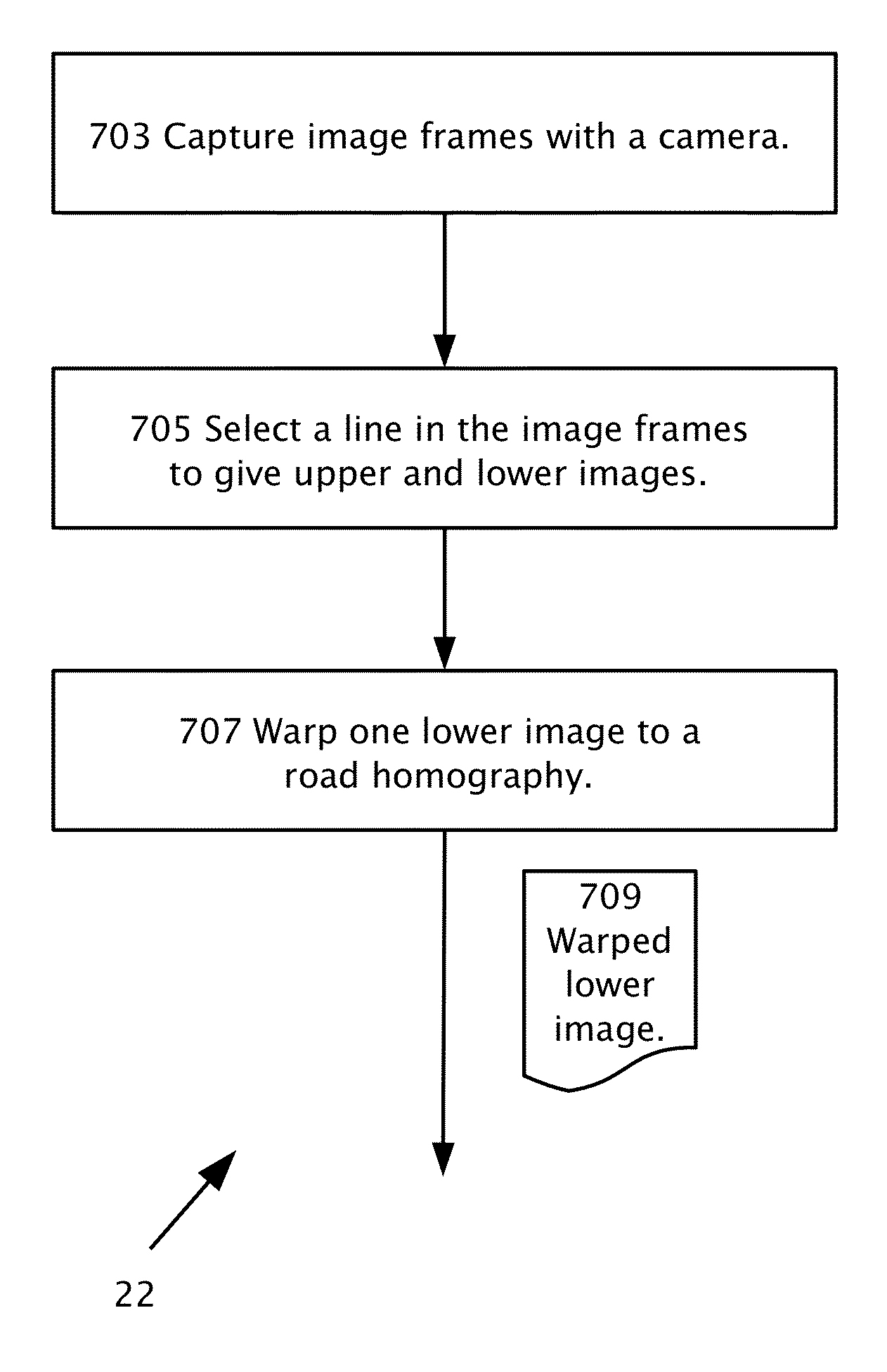
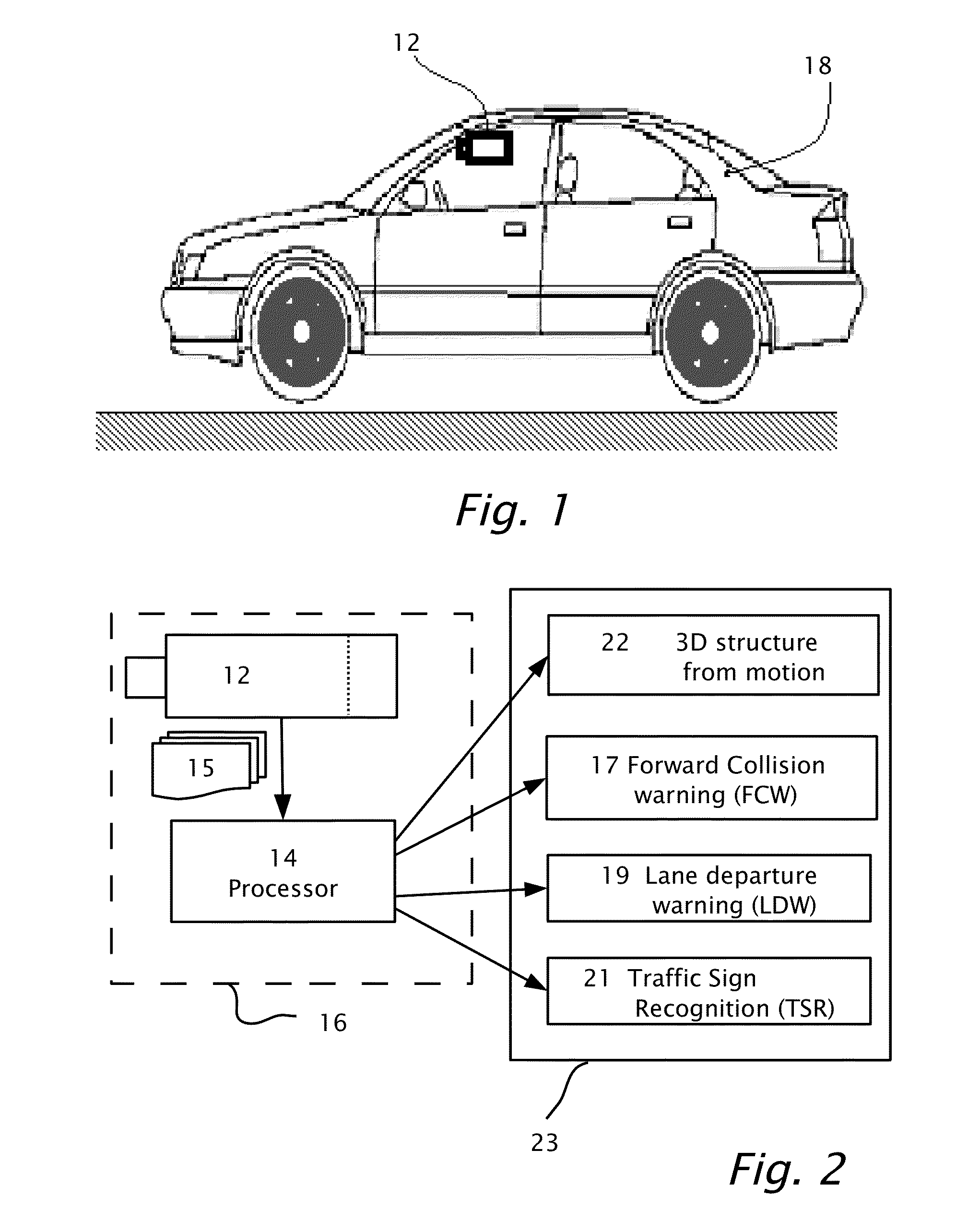
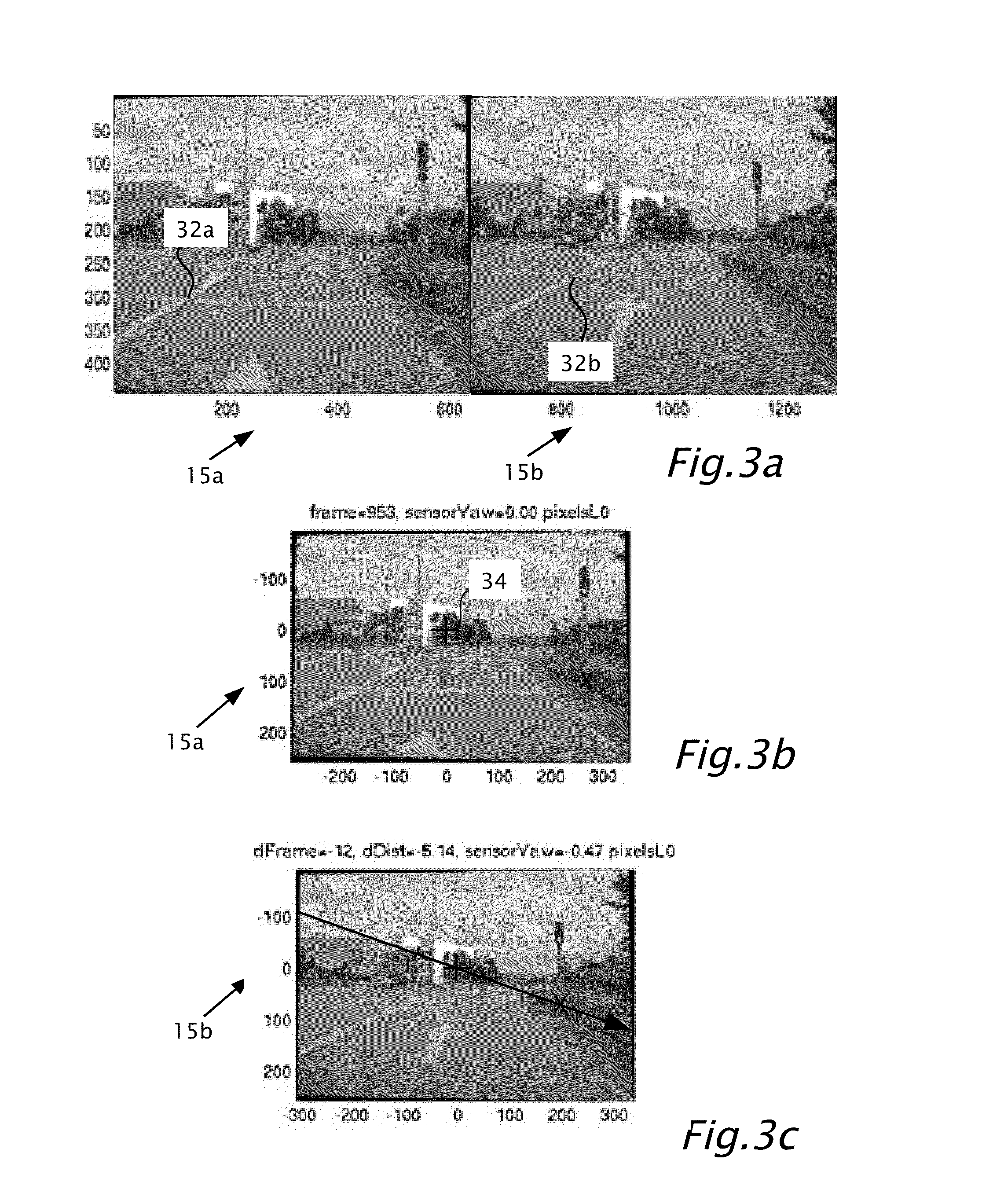
The patent describes a system for determining the shape of a road environment using a camera and image processing techniques. The system captures multiple image frames and selects a line to extract the road from the images. The lower images are warped based on the road's homography to match the upper images. The system matches features between the frames using image matches to create a three-dimensional structure of the road. This system can be mounted on a vehicle and used to assist in vehicle navigation. The system can also use image frames captured at different times or distances to track the movement of features in the road environment.

Problems solved by technology

Finding structure from motion presents a similar problem as finding structure from stereo vision.

Method used


Image

  • Dense structure from motion
  • Dense structure from motion
  • Dense structure from motion

Examples


Embodiment Construction

[0030]Reference will now be made in detail to embodiments of the present invention, examples of which are illustrated in the accompanying drawings, wherein like reference numerals refer to the like elements throughout. The embodiments are described below to explain the present invention by referring to the figures.

[0031]Before explaining embodiments of the invention in detail, it is to be understood that the invention is not limited in its application to the details of design and the arrangement of the components set forth in the following description or illustrated in the drawings. The invention is capable of other embodiments or of being practiced or carried out in various ways. Also, it is to be understood that the phraseology and terminology employed herein is for the purpose of description and should not be regarded as limiting.

[0032]By way of introduction, embodiments of the present invention may be directed to images from a camera moving through space which may provide rich i...


PUM


Abstract

Determining three-dimensional structure in a road environment using a system mountable in a host vehicle including a camera connectible to a processor. Multiple image frames are captured in the field of view of the camera. In the image frames, a line is selected below which the road is imaged. The line separates between upper images essentially excluding images of the road and lower images essentially including images of the road. One or more of the lower images is warped, according to a road homography to produce at least one warped lower image. The three-dimensional structure may be provided from motion of a matching feature within the upper images or from motion of a matching feature within at least one of the lower images and at least one warped lower image.

Description

CROSS REFERENCE TO RELATED APPLICATIONS[0001]The present application is a continuation-in-part application of U.S. patent application No. 13 / 693,713 filed on 4 Dec. 2012 and also a continuation-in-part U.S. patent application Ser. No. 13 / 237,163 filed on 20 Sep. 2011, the disclosures of which are incorporated by reference as if entirely set forth herein. The present application claims priority from U.S. provisional patent application 61 / 766,738 filed on 20 Feb. 2013 and U.S. provisional application 61 / 767,321 filed on 21 Feb. 2013 by the same inventors the disclosures of which are incorporated by reference as if entirely set forth herein.BACKGROUND[0002]1. Technical Field[0003]The present disclosure relates to computing accurate dense structure from motion in the automotive environment.[0004]2. Description of Related Art[0005]Structure-from-Motion (SfM) refers to methods for recovering three-dimensional information of a scene that has been projected onto the focal plane of a camera....

Claims


Application Information

Patent Timeline
IPC IPC(8): G06T3/00G06K9/62G06T7/20
CPCG06T3/0093G06T7/20G06K9/6201G06T2207/10016G06T2207/30256G06T7/579G06V20/588G06F18/22G06T3/18
Inventor LIVYATAN, HARELBERBERIAN, ODEDCOHEN, BARAKSTEIN, GIDEON
Owner MOBILEYE VISION TECH LTD
Learn More