
Device and Method for Degassing of Liquids

a liquid degassing and liquid technology, applied in the direction of isotope separation, separation process, dispersed particle separation, etc., can solve the problems of gas bubble formation, inefficient method, and gas bubble formation

Inactive Publication Date: 2014-06-12
STRATEC BIOMEDICAL AG
View PDF10 Cites 18 Cited by
  • Summary
  • Abstract
  • Description
  • Claims
  • Application Information

AI Technical Summary

Benefits of technology

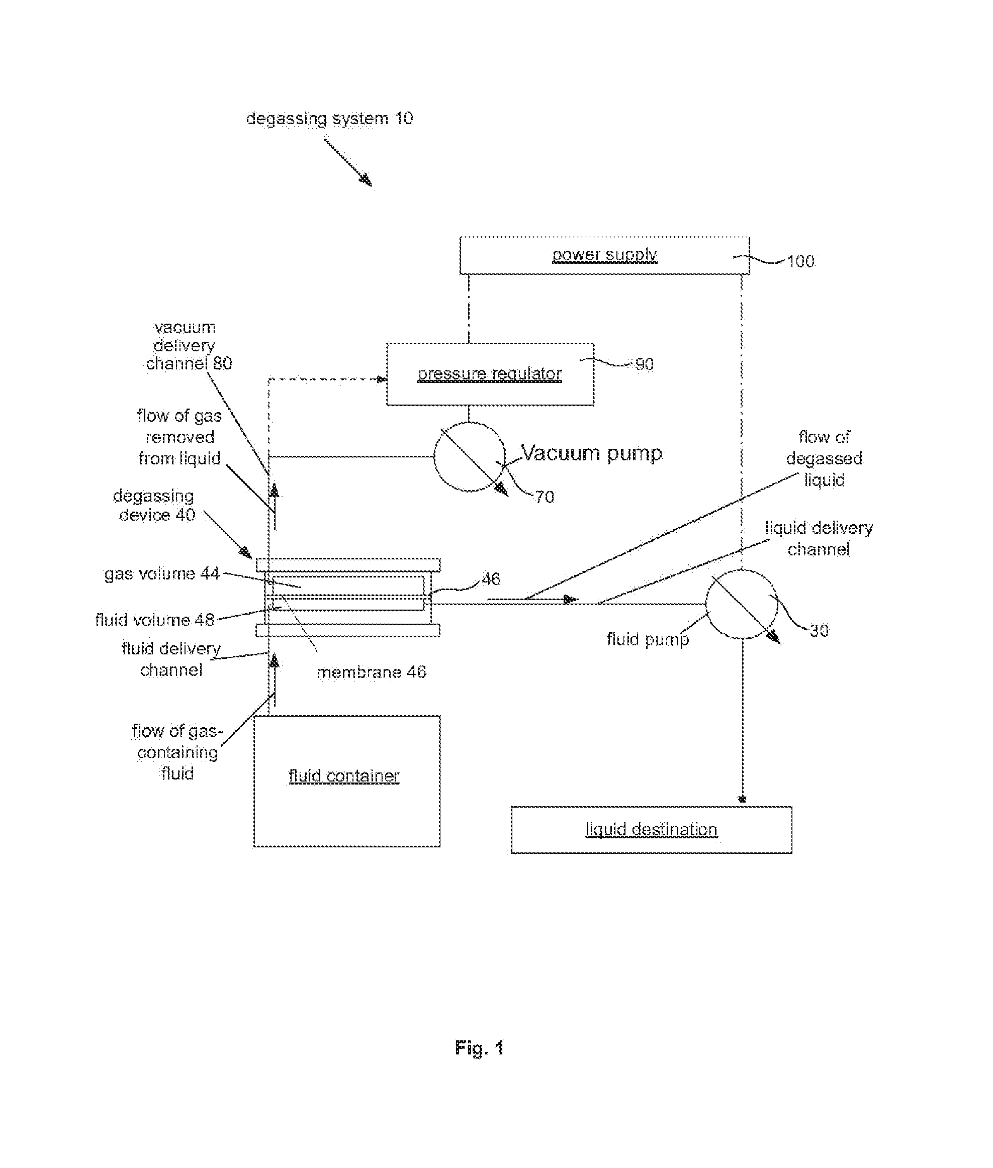
The patent describes a modular degassing device and method for removing gases from fluids such as water. The device consists of outer clamping plates with a degassing module in between, which uses a membrane and vacuum pressure to remove gases from the fluid. The device can be configured in different ways to increase efficiency and can be connected to a vacuum pump and pressure regulator. The method involves separating fluid channels and vacuum channels using a membrane, drawing the fluid through the channels with a vacuum, and withdrawing the gases from the vacuum channels. The technical effects of this invention include improved efficiency, flexibility, and ease of use for degassing fluids.

Problems solved by technology

The inlet side of a vacuum pump can create a local vacuum causing a pressure imbalance leading to a liberation of the gasses from the fluid.
Also, as a result of pump-related negative pressures, pipetting systems used for fluid analysis and diagnoses are prone to pressure differences leading to the formation of the gas bubbles.
This method is inefficient, requires large tanks, and is limited in its flow rate due to the tank size.
This method proves to be not reasonably compact enough for many settings due to the flow rates needed.
This thermal degassing method is obviously not possible for fluids for which heating damages or alters critical characteristics of the fluids.
However, the addition of chemicals and stripping gasses may contaminate the fluids, and the latter method will still leave the stripping gas in the fluid.
Heating and contaminating methods are poor degassing choices for those fluids for which the integrity of the fluid characteristics is critical.
This method can only be applied on fluids with a sufficiently high viscosity, such as some oils or resins, and is not useful for fluids with insufficient viscosities.
This method is better suited to remove free gasses (i.e., gas bubbles, rather than dissolved gasses), and is the most expensive method due to the ultrasonic components required.
There are also contactor-type hollow fiber degassers that can reach a flow rate of about 600 ml / minute, but the contactor-type hollow fiber degassers are complex and expensive.

Method used


Image

  • Device and Method for Degassing of Liquids
  • Device and Method for Degassing of Liquids
  • Device and Method for Degassing of Liquids

Examples


Embodiment Construction

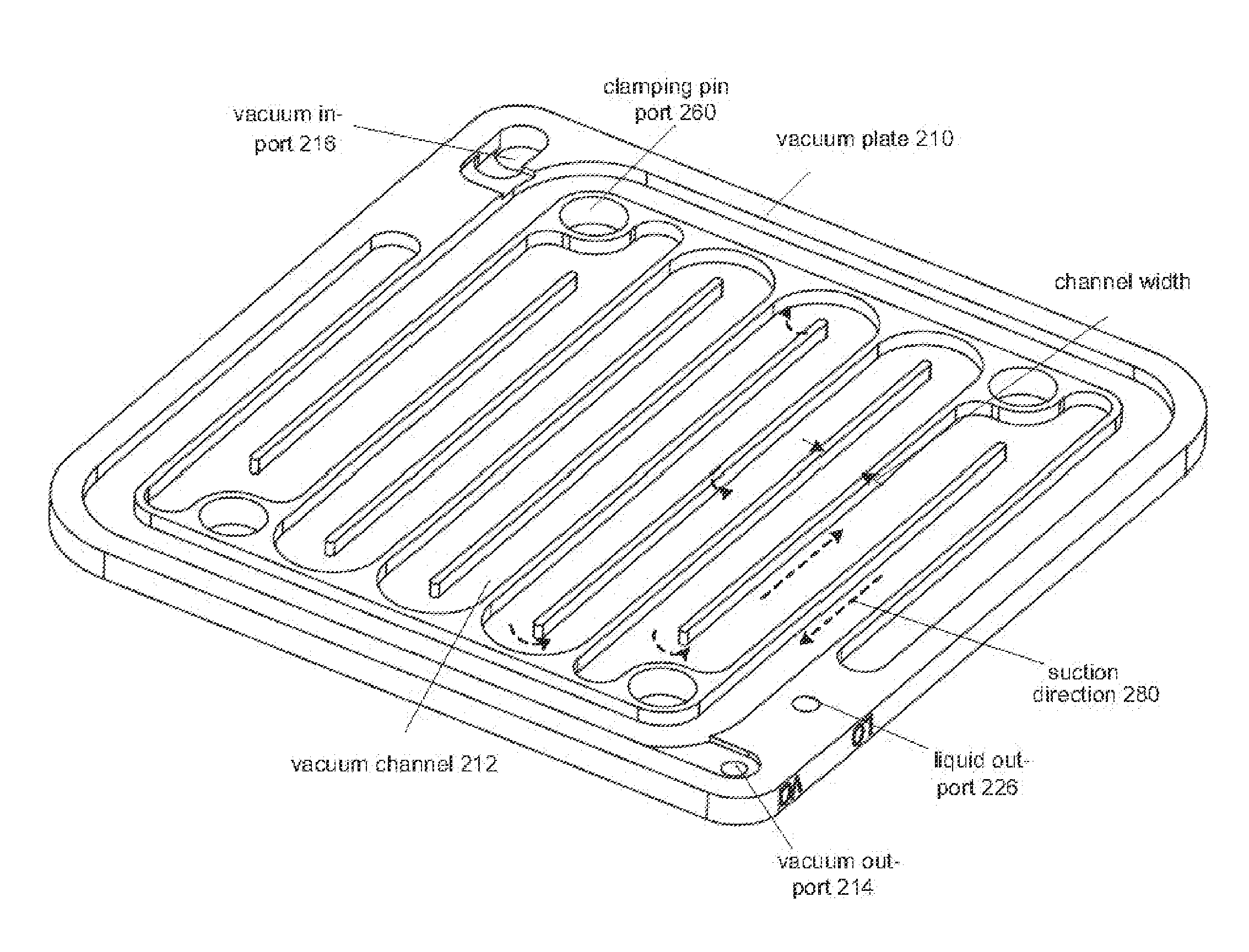
[0040]A modular degassing device and method for degassing a fluid are disclosed that apply vacuum on the fluid (e.g., water) to change the ambient pressure to change the concentration of dissolved gasses. The vacuum can be applied to the fluid to shift the balance between the ambient pressure and the partial pressure of the gasses dissolved in the water to such an extent that the gas concentration in the fluid drops to an acceptable level, (e.g., degassing the fluid).

[0041]According to this disclosure, a fluid is to understood as any substance capable of flowing in response to a drawing and / or pressing force. A fluid according to this disclosure can be a liquid of any viscosity or a gas.

[0042]Further, according to this disclosure, a channel is to be understood as a guide capable of guiding a fluid flowing along a path. A channel according to this disclosure may be a path recessed within a plate and / or within a membrane covering the plate.

[0043]Fluid can be conveyed into the modular ...


PUM

PropertyMeasurementUnit
Forceaaaaaaaaaa
Hydrophobicityaaaaaaaaaa

Abstract

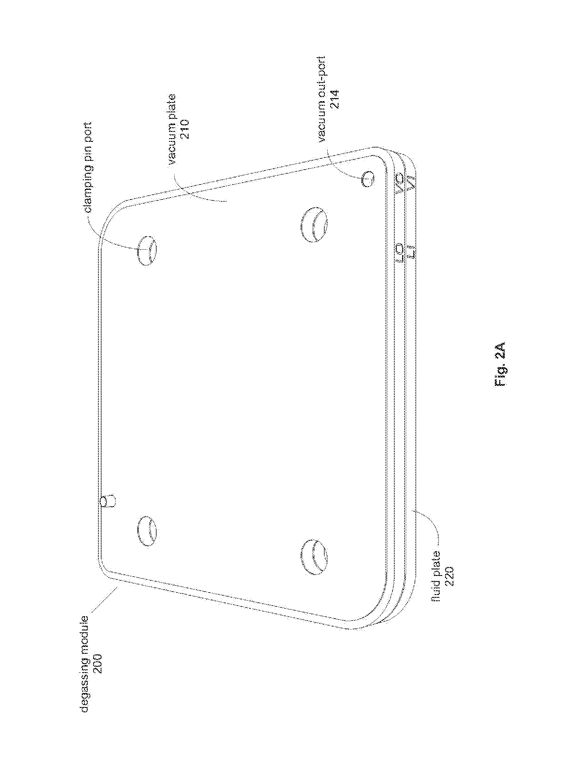
A modular degassing device (40) is disclosed. The modular degassing device (40) comprises outer clamping plates (330, 340) with at least one degassing module (200) arranged therebetween, wherein the degassing module (200) comprises two modular plates (310, 320) adjacently arranged, both modular plates (310, 320) having a first channel on sides facing a membrane (46) placed therebetween, wherein the first channel of one modular plate (310, 320) is a fluid channel (224) on one side of the membrane (46), and the first channel of the other modular plate (310, 320) is a vacuum channel (212) on the other side of the membrane (46).

Description

BACKGROUND[0001]1. Field of the Invention[0002]Devices and methods for degassing liquid media in diagnostic systems are disclosed. For example, devices and methods for removing free and dissolved gas mixtures, such as air, from fluid media, such as water, to be used in diagnostic systems are disclosed. The devices and methods can utilize vacuum-dependent removal of gasses from the fluids in the diagnostic systems. The device can be constructed a modular device.[0003]2. Description of the Related Art[0004]Gasses are typically contained in fluids, for example in water. The gasses are usually present in a free or undissolved phase, i.e. as minuscule gas bubbles, and also in a dissolved state in the fluid. The concentration of these dissolved gasses depends on a number of factors, such as the ambient pressure, the temperature or the salinity. In analytical and diagnostic systems specific process steps involving a change in pressure or temperature can cause gasses to dissolve in or evapo...

Claims


Application Information

Patent Timeline
IPC IPC(8): B01D19/00
CPCB01D19/0031B01D19/0021B01D19/0036
Inventor TRUMP, MARTINBARENTHIN, VOLKER
Owner STRATEC BIOMEDICAL AG
Learn More