Method and fossil-fuel-fired power plant for recovering a condensate

a technology of condensate and power plant, which is applied in the direction of machines/engines, separation processes, lighting and heating apparatus, etc., can solve the problems of high investment and operating costs, high operating costs, and invariably continuously evaporated water, so as to reduce the cost of installation and operation of demin-water treatment plants.

Inactive Publication Date: 2014-06-05
SIEMENS AG
View PDF1 Cites 5 Cited by
  • Summary
  • Abstract
  • Description
  • Claims
  • Application Information

AI Technical Summary

Benefits of technology

[0009]It is therefore an object herein to provide a fossil-fired power plant by which the costs for the installation and the operation of a demin-water treatment plant can be reduced despite installation of CO2 separation apparatus which is connected to the power plant. It is also an object herein to provide a method for recovery of condensate, as a result of which the demin-water treatment plant of a power plant with associated CO2 separation apparatus can be relieved of load.

Problems solved by technology

During operation of the CO2 capture process, however, some of the water invariably continuously evaporates.
For provision of this water, high costs are partly incurred.
In power plants which are retrofitted with CO2 separation apparatus a demin-water treatment plant must also be provided at the same time, bringing with it high investment and operating costs.

Method used


Image

  • Method and fossil-fuel-fired power plant for recovering a condensate
  • Method and fossil-fuel-fired power plant for recovering a condensate
  • Method and fossil-fuel-fired power plant for recovering a condensate

Examples


Embodiment Construction

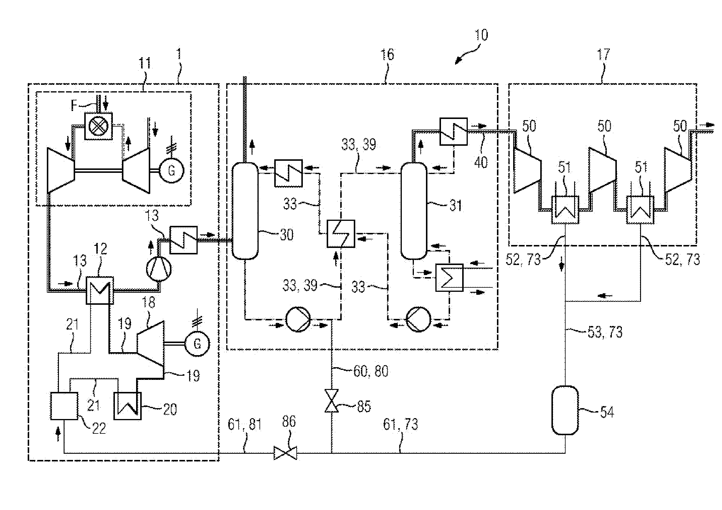
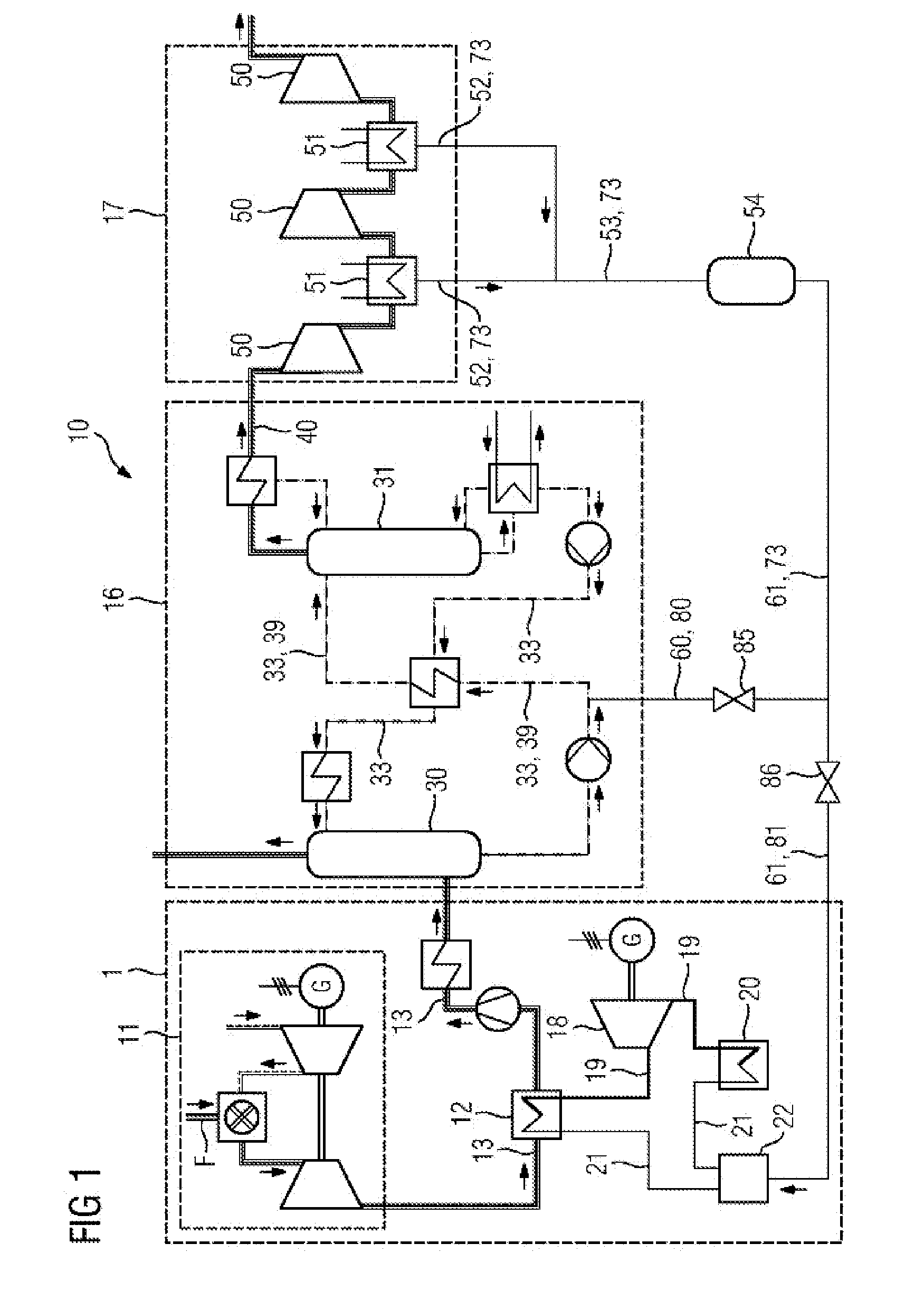
[0024]FIG. 1 shows a fossil-fired power plant 10, with a gas turbine plant as combustion apparatus 11, a heat recovery steam generator 12 which, via a flue gas duct 13, is connected downstream to the gas turbine of the combustion apparatus 11, a condenser 20, a demin-water treatment plant 22, CO2 separation apparatus 16 which is connected into the flue gas duct 13, and a compressor 17, having a number of compressor stages and intercooling stages 50, 51, which is connected downstream to the CO2 separation apparatus 16.

[0025]In the gas turbine plant of the combustion apparatus 11, a fossil fuel is combusted, wherein flue gas containing CO2 is formed. The flue gas is fed to the heat recovery steam generator 12 via a flue gas duct 13 for producing steam 19. The steam 19 is fed in turn to a steam turbine plant 18, which is not shown in more detail here, where it is expanded, is then fed to a condenser 20, and expanded to form feed water 21. After the condensing of the steam 19 in the con...


PUM


Abstract

A fossil-fuel-fired power plant, having a combustion device, a CO2 separation device, which is arranged downstream of the fossil-fuel-fired power plant, for removing CO2, and a CO2 compressor station, which is arranged downstream of the CO2 separation device and which has a number of compressor stages and coolers for intermediate cooling is provided. The coolers are connected to the CO2 separation device or the fossil-fuel-fired power plant by means of a condensate line in order to recover condensate. A method for carrying out the condensate recovery is also provided.

Description

CROSS REFERENCE TO RELATED APPLICATIONS[0001]This application is the U.S. National Stage of International Application No. PCT / EP2012 / 064522 filed Jul. 24, 2012, and claims the benefit thereof. The International Application claims the benefit of European Application No. EP11175948 filed Jul. 29, 2011. All of the applications are incorporated by reference herein in their entirety.FIELD OF INVENTION[0002]The present invention relates to a fossil-fuel fired power plant for recovering a condensate and methods therefor.BACKGROUND OF INVENTION[0003]In fossil-fired power plants for generating electric energy, a flue gas containing carbon dioxide is produced as a result of the combustion of a fossil fuel. For avoiding or for reducing carbon dioxide emissions, carbon dioxide must be separated from the flue gases. For separating carbon dioxide from a gas mixture, different methods are universally known. In particular, for separating carbon dioxide from a flue gas after a combustion process, th...

Claims


Application Information

Patent Timeline
Patent Type & Authority Applications(United States)
IPC IPC(8): B01D53/14B01D53/00F23J15/02
CPCB01D53/1475F23J15/02B01D53/002F01K23/10Y02C20/40Y02E20/32
Inventor SCHNEIDER, RUDIGERSCHRAMM, HENNING
Owner SIEMENS AG
Why Eureka
Try Eureka