Semi-passive resistance force control system with active augmentation

a control system and passive resistance technology, applied in the direction of gymnastic exercise, sport apparatus, cardiovascular exercise devices, etc., can solve the problems of not providing constant resistance force, and not meeting users' needs

Inactive Publication Date: 2014-05-29
STRENGTH MASTER FITNESS TECH
View PDF12 Cites 0 Cited by
  • Summary
  • Abstract
  • Description
  • Claims
  • Application Information

AI Technical Summary

Benefits of technology

[0010]The coupler comprises a first revolving wheel, a second revolving wheel, a third revolving wheel coaxially; the first revolving wheel is mechanically connected to the piston resistance force module to convert the output resistance force of the piston resistance force module into a first torque; the third revolving wheel is mechanically connected to the electrical motor to convert the adjustment resistance force into a second torque; the second revolving wheel is mechanically connected to the pulling part to convert the first torque and the second torque through a common axis to output the desired resistance force to the pulling part. The radius ratio of the first revolving wheel, the third revolving wheel, and the second revolving wheel is decided by the ratio and magnitudes of the output resistance force of the piston resistance force module, the adjustment force of the electrical force, and the desired resistance force.
[0011]Furthermore, the control module decides to open or close the source control valve and the vent control valve based on the preset gas pressure and the electrical signal of the gas pressure sensor to make the gas supply module achieve the preset gas pressure, in turns to generate a preset resistance force, the control module is also able to dynamically adjust the preset gas pressure of the gas supply module to adjust the preset resistance force; the control module derives a force difference between the output resistance force and the preset resistance force through the gas pressure deviation detected by the gas pressure sensor during the movement of the piston; the control module utilizes the movement distance of the pulling part detected by the position sensor and a second control mode to generate an active adjustment value, then the control module derive the adjustment resistance force based on the force difference and the active adjustment value.
[0012]As above-mentioned, the semi-passive resistance force control system with active augmentation of the present invention may have one or more characteristics and advantages as described below:
[0013](1) The present invention comprises a gas reservoir such that the output resistance force of the piston resistance force module follows a more stable preset mode through the gas interconnection of the gas supply module with the piston resistance force module.
[0014](2) The present invention comprises a gas pressure sensor such that the gas pressure change due to the movement of the piston is detected instantly, and then the electrical signal of the gas pressure sensor is transferred to the control module. Based on the electrical signal of the gas pressure sensor, the control module controls the resistance force adjustment module to actively compensate the deviation of the output resistance force due to the gas pressure change such that the output resistance force remained fixed.
[0015](3) The present invention comprises a position sensor such that the movement distance of the pulling part is detected instantly when the piston of the piston of the piston resistance force module is pulled, and then the electrical signal of the position sensor is transferred to the control module. Based on the electrical signal of the position sensor, the control module executes an active adjustment to the output resistance force in according with a second preset mode such that the user can experience a desired resistance force.

Problems solved by technology

However, the pure passive resistance force system of the current sport facility cannot supply a constant resistance force when a user pulls a pulling part of the sport facility, nor does it meet users' requirement of dynamically adjusting the compensated resistance force during a sport stroke.
Thus, it cannot fulfill the above purpose.

Method used


Image

  • Semi-passive resistance force control system with active augmentation
  • Semi-passive resistance force control system with active augmentation
  • Semi-passive resistance force control system with active augmentation

Examples


Embodiment Construction

[0019]With reference to the drawings, thereafter, the preferred embodiments of a semi-passive resistance force control system with active augmentation in accordance with the present invention are illustrated. In order to be understood easily, the same components in the following embodiments are labeled as the same numeral.

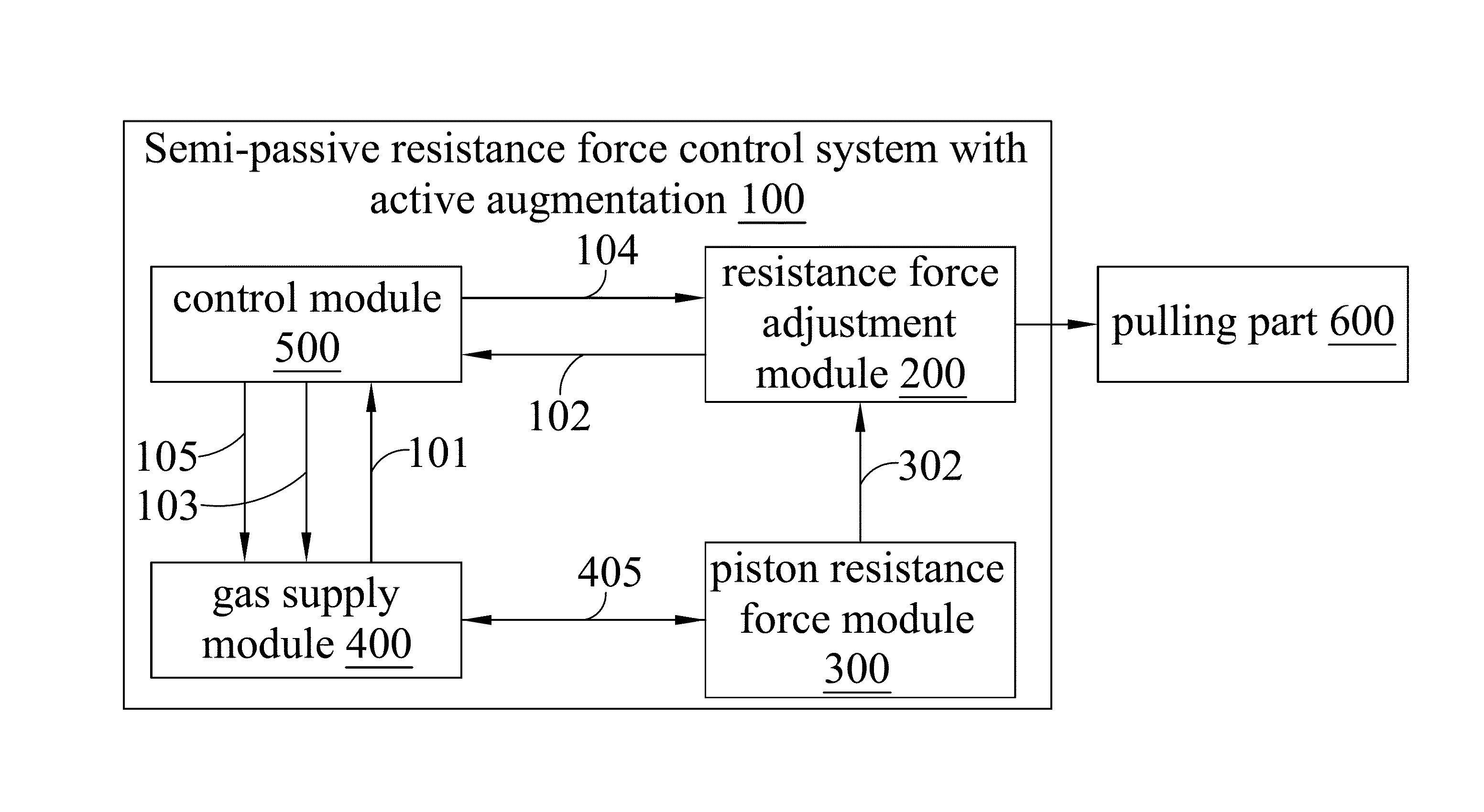
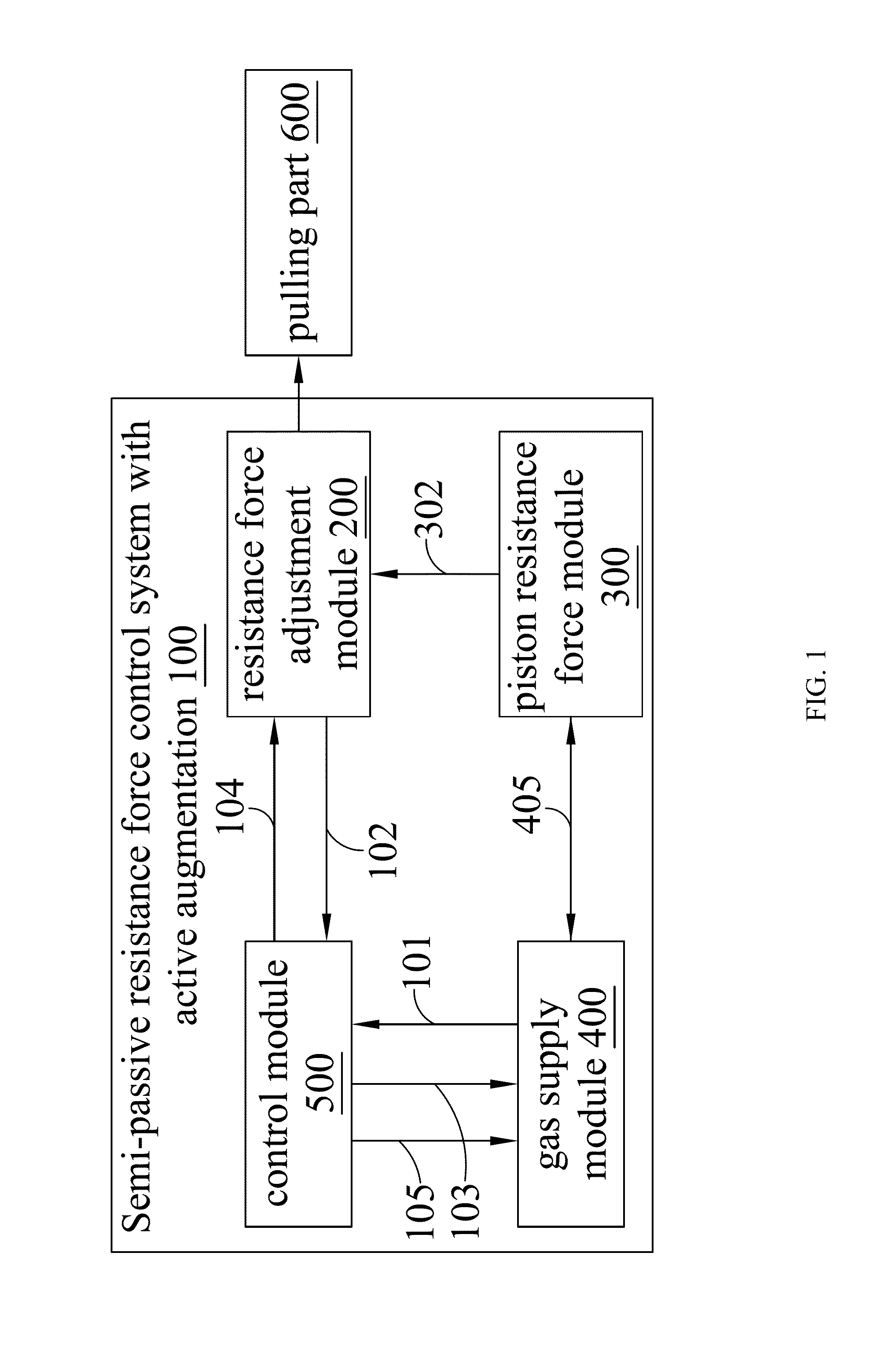
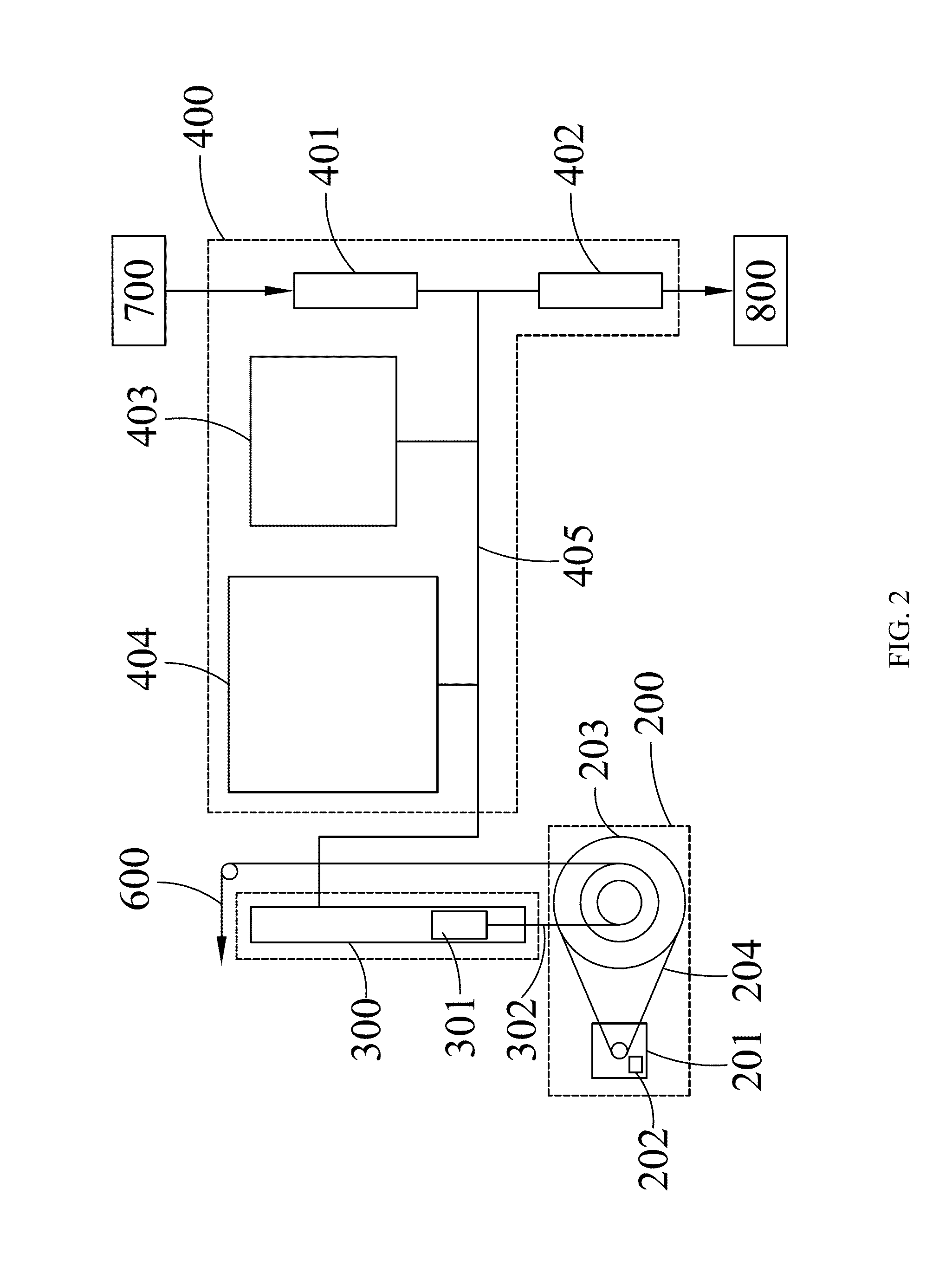
[0020]The present discloses a semi-passive resistance force control system with active augmentation, which is suitable for a sport equipment with a pulling part. The semi-passive resistance force control system with active augmentation comprises a resistance force adjustment module, an energy neutral apparatus, and a control module. The energy neutral apparatus not only provides an output resistance force to the pulling part when the pulling part is pulled by a user, but also reduces the change of the output resistance force due to the piston movement. Based on the detection data of the system internal sensors during the movement of the pulling part, the control mo...


PUM


Abstract

Disclosed is a semi-passive resistance force control system with active augmentation, which is suitable for a sport equipment with a pulling part. This semi-passive resistance force control system with active augmentation comprises a resistance force module, an energy neutral apparatus, and a control module. The energy neutral apparatus can not only provide an output resistance force to the pulling part when the pulling part is pulled by a user, but also reduce the variation of the output resistance force. The control module is able to accept the sensing data delivered by the internal sensors of the semi-passive resistance force control system with active augmentation to passively compensate the output resistance force and make it fixed. Furthermore, the control module can also provide an active adjustment to the output resistance force based on a preset control mode such that the user can experience a desired resistance force.

Description

BACKGROUND OF THE INVENTION[0001]1. Field of the Invention[0002]The present invention relates to a semi-passive resistance force control system with active augmentation, and particularly, a semi-passive resistance force control system with active augmentation suitable to a sport equipment with a pulling part.[0003]2. Description of the Related Art[0004]Currently, the fast development of electronics and electric-driven machines drives the evolution of the sport facility, which triggers normal users to pursuit functional and personal needs on sport facility. However, the pure passive resistance force system of the current sport facility cannot supply a constant resistance force when a user pulls a pulling part of the sport facility, nor does it meet users' requirement of dynamically adjusting the compensated resistance force during a sport stroke. Thus, it cannot fulfill the above purpose.BRIEF SUMMARY[0005]Based on the problems of the prior arts, one of the objects of the present inv...

Claims


Application Information

Patent Timeline
Patent Type & Authority Applications(United States)
IPC IPC(8): A63B24/00
CPCA63B24/0087A63B21/0058A63B21/0087A63B21/023A63B22/0605A63B2220/10A63B2220/56
Inventor CHANG, CHAO-KOURAHIM, WADIATUR
Owner STRENGTH MASTER FITNESS TECH
Why Eureka
Try Eureka