
Method and system for dental implant surgical guides

a surgical guide and dental implant technology, applied in dental implants, dental surgery, medical science, etc., can solve the problems of inability to meet the needs of patients, inability to offer surgical guide manufacturing services at reasonable price, and low batch volume of specific drilling sleeves

Inactive Publication Date: 2014-05-29
GAO FEI
View PDF3 Cites 6 Cited by
  • Summary
  • Abstract
  • Description
  • Claims
  • Application Information

AI Technical Summary

Benefits of technology

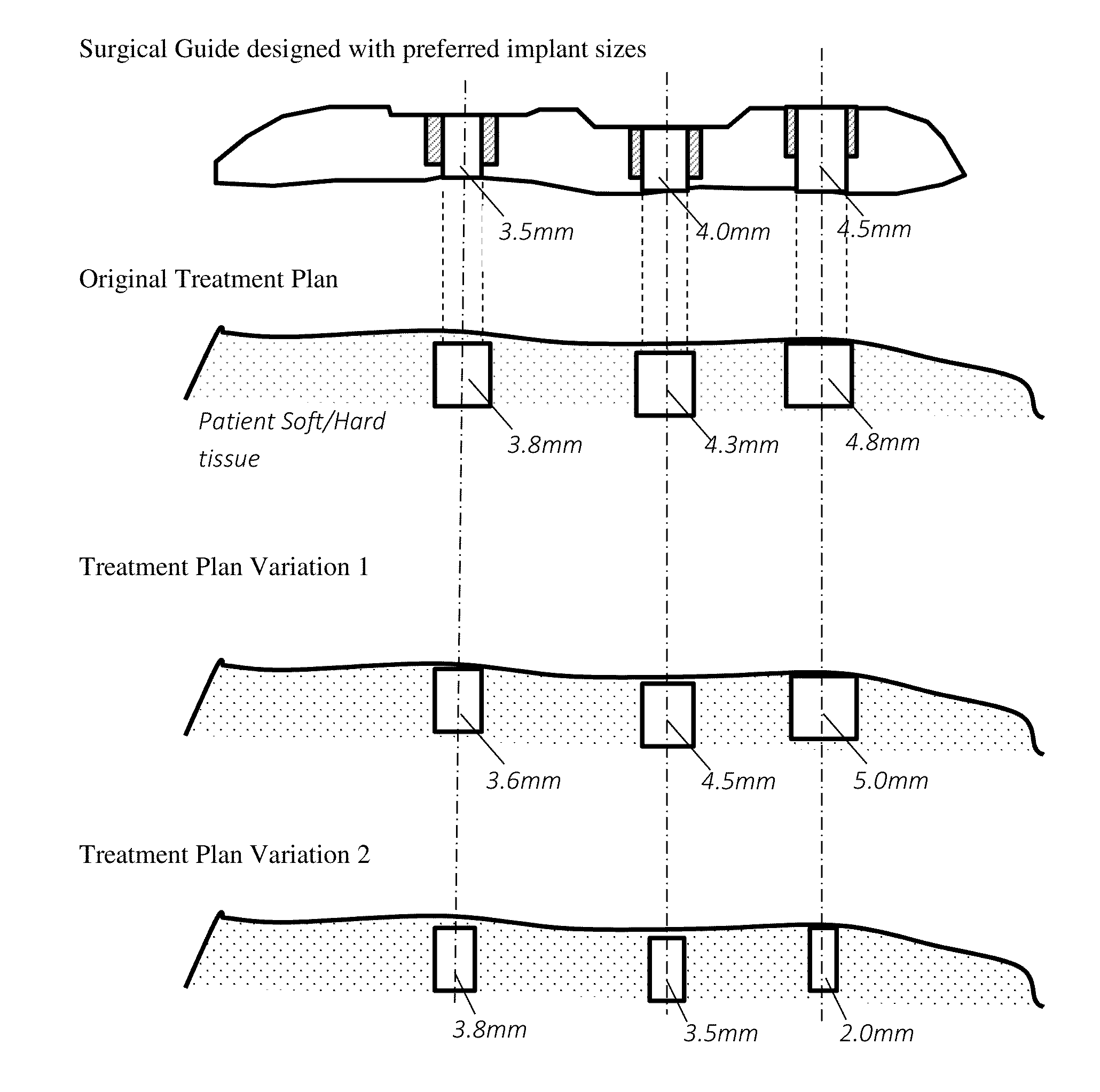
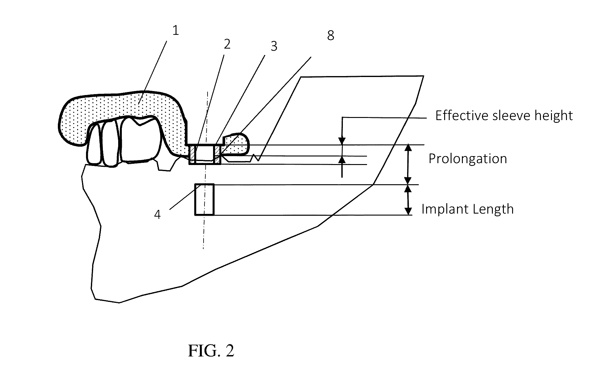
The invention is a surgical guide designed to improve the accuracy and efficiency of drilling implant holes in patient's anatomy. The guide is based on a base model and has drill guiding holes with preferred diameters that can accommodate different implant diameters. The guide also includes a prolongation value that can be customized to improve the guidance of drilling operations. The guide design and a universal surgical kit with drills and drilling keys based on the preferred diameters can be used in computer-assisted surgery. The technical effects of the invention include improved accuracy and efficiency of drilling implant holes and reduced surgery duration.

Problems solved by technology

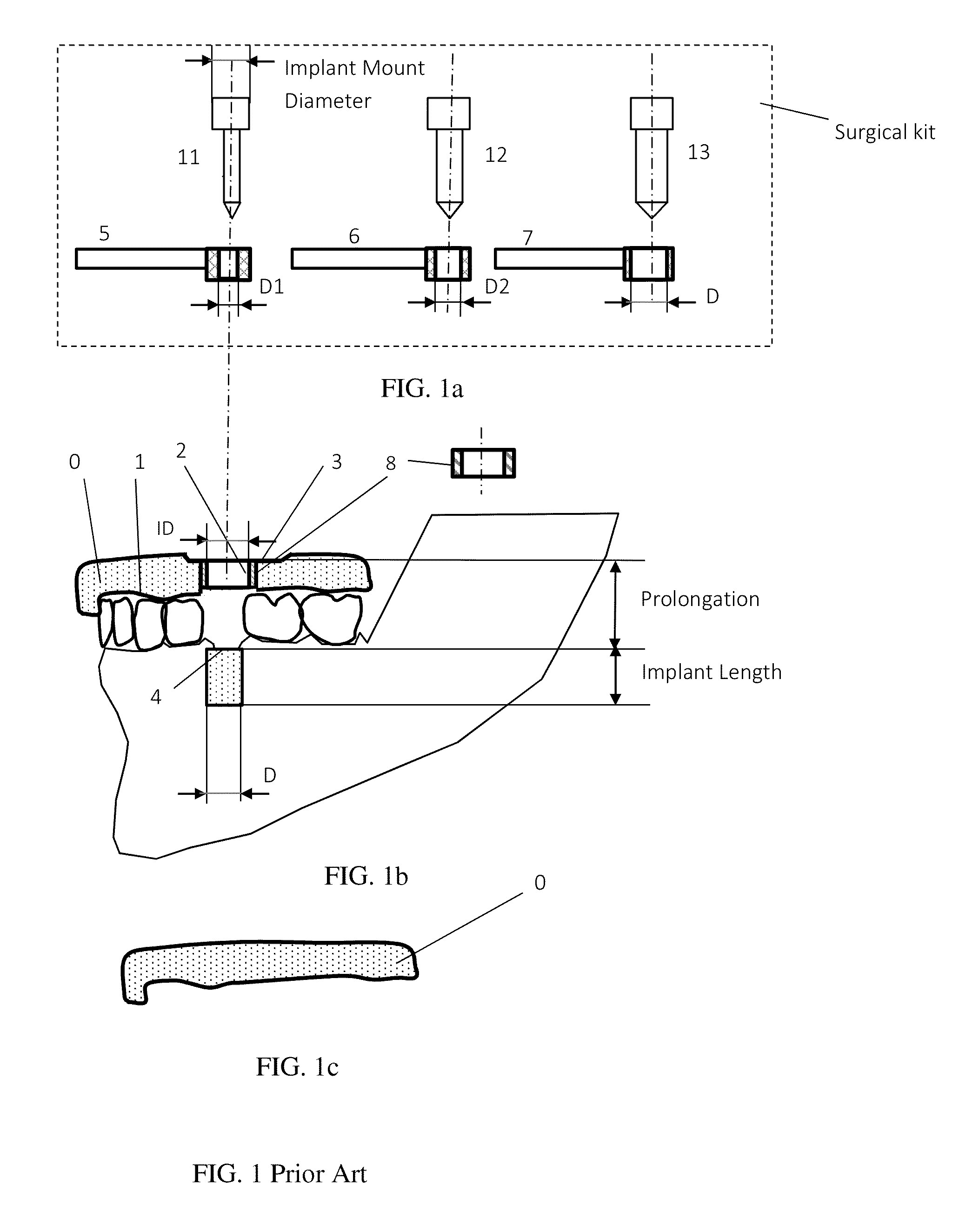
There are flexibility issues with such an approach where a surgical guide is designed for the surgical kit corresponding to implant brands.
If he / she wants to mix implant platforms, he / she has to get all kinds of surgical kits, which is however not practical because there are so many implant manufacturers, each of them has various implant sizes, and there is no standard size series in the industry, nor universal surgical kits.
In most situations, the batch volume of specific drilling sleeves is extremely low, which practically prevents small manufacturers or dental labs from offering surgical guide manufacturing services at reasonable price.

Method used


Image

  • Method and system for dental implant surgical guides
  • Method and system for dental implant surgical guides
  • Method and system for dental implant surgical guides

Examples


Embodiment Construction

The method

[0029]In surgical guide design, a base model will be first created to fit onto the patient anatomy before geometric features are added. There have been various approaches to generate a base model, and to add additional form features. This is not the topic of this invention, so it is assumed that a base model has been created. Usually drilling sleeves will be inserted into a surgical guide model. They can prevent the guide from being cut. There could be various designs of the sleeves. This invention does not limit the actual geometric design of the drilling sleeves. Only the three key parameters of a guide-drilling hole or sleeve are concerned: inner diameter, thickness, and height.

[0030]Implant diameters vary from one manufacturer to another. There is no standard dimension series. Surgical guides and their targeted surgical kits from manufacturers are designed to drill implant holes to those diameters.

[0031]A series of diameters are defined as an arithmetic progression in ...


PUM


Abstract

A dental implant surgical guide, its design method and system. A surgical guide has an adaption surface to fit onto patient's oral dental anatomy, as well as holes to guide the drills and to provide depth control to the drilling operations. In prior art, drill guiding holes have to be specifically designed and made for a targeted surgical kit. In this invention, a series of preferred diameters are predefined for the drilling holes or sleeves, a surgical guide is designed for the preferred diameters and a universal surgical kit is designed accordingly. Indexing geometric features are added to the surgical guide to indicate the key parameters for drilling depth control. As a result the surgical guide and universal surgical kit can be used with any implant brands. Software system designing such surgical guides includes components to generate base model, define and select preferred diameters, add form features, and export treatment plan with plan adaption instructions.

Description

CROSS-REFERENCE TO RELATED APPLICATIONS[0001]Fei Gao 12 / 795,045 July 2010REFERENCE CITEDUS Patent Documents[0002]Karkar, et al.2010 / 0105011April 2010Michael Poirier6,814,575September 2004Trevor Bavar8,105,081 B2January 2012Bart Swaelens, et al.5,768,134October 1996Daniel R. Llop et al12 / 683,319January 2010Jerome Haber12 / 818,522January 2010Other Publications[0003]NobelBiocare, NobelGuide: Concept manual for guided surgery, 2011U.S. Classification: 433 / 75[0004]Field of search: 433 / 72, 75, 76 433 / 172,173FIELD OF THE INVENTION[0005]This invention concerns the surgical guide design and accompanying surgical kits for image-guided dental implant treatment. A surgical guide is usually designed according to the specification of a selected surgical kit and implant platform. In this invention the surgical guides are designed independent of implant brands and their surgical kits, used with a universal surgical kit, and can be adapted even if treatment plans have to be modified after the guides ...

Claims


Application Information

Patent Timeline
Patent Type & Authority Applications(United States)
IPC IPC(8): A61C8/00
CPCA61C8/009A61C1/084
Inventor GAO, FEI
Owner GAO FEI
Learn More