
Clinical ambient control system

a control system and ambient technology, applied in the field of clinical ambient control system, can solve the problems of inability to fully focus clinical personnel, time-consuming and inconvenient adjustment of appliances, and achieve the effect of improving patient examination

Active Publication Date: 2014-05-22
KONINKLJIJKE PHILIPS NV
View PDF2 Cites 3 Cited by
  • Summary
  • Abstract
  • Description
  • Claims
  • Application Information

AI Technical Summary

Benefits of technology

The patent is for a system that improves patient examinations using scanners. It aims to automate adjustment actions that are required during the examination. The system is designed to move the bed where the patient is scanned, and it includes an ambient control system that can manage the scanning process. The technical effect is that the system streamlines the examination process, making it more efficient and comfortable for patients.

Problems solved by technology

The adjustment of appliances may be time consuming and inconvenient for the examination.
Accordingly, it is a problem that clinical personnel may not be able to focus fully on the examination itself, but may also need to perform adjustments and adaptations of various appliances used in the scanner room.

Method used


Image

  • Clinical ambient control system
  • Clinical ambient control system
  • Clinical ambient control system

Examples


Embodiment Construction

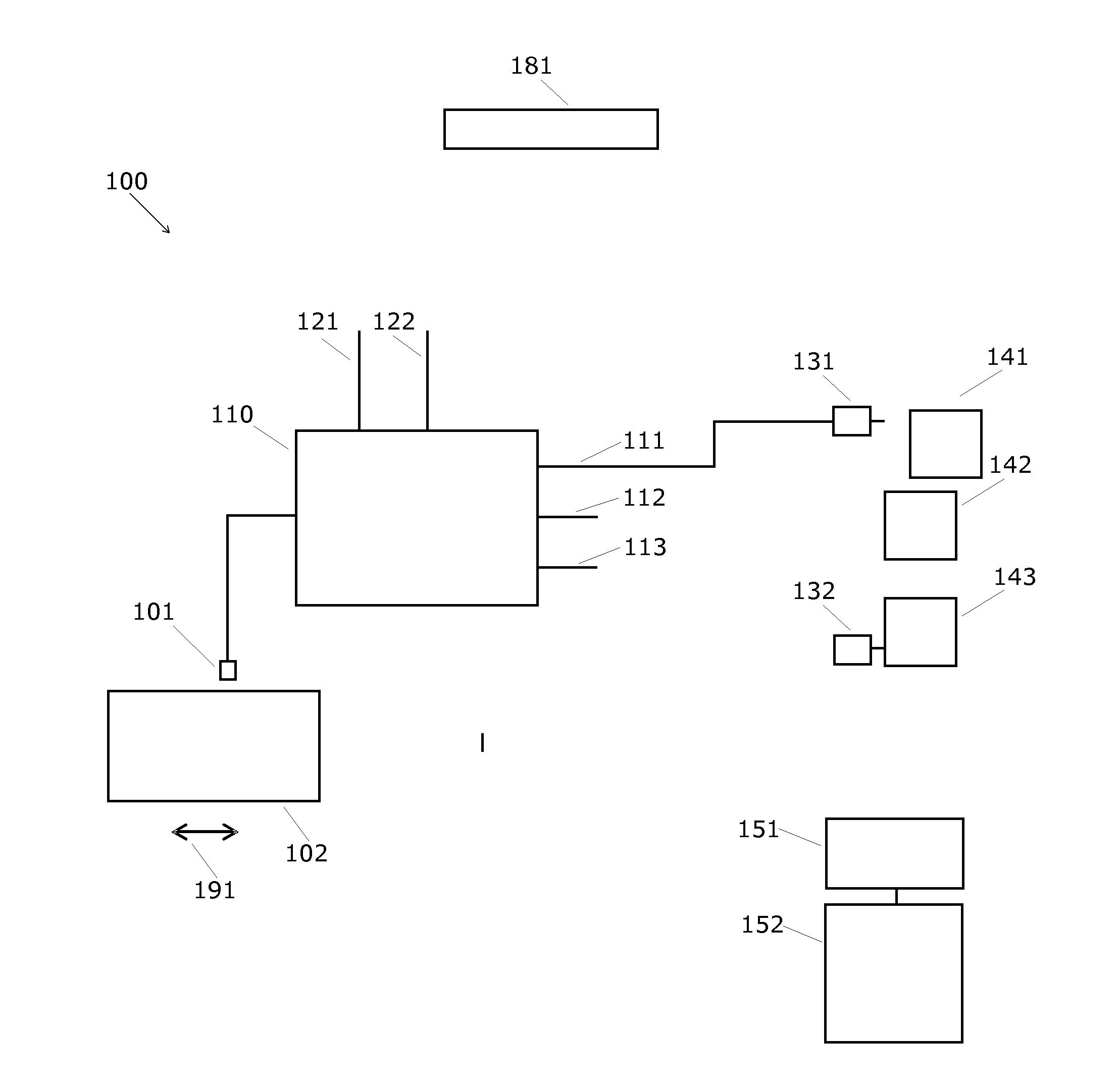
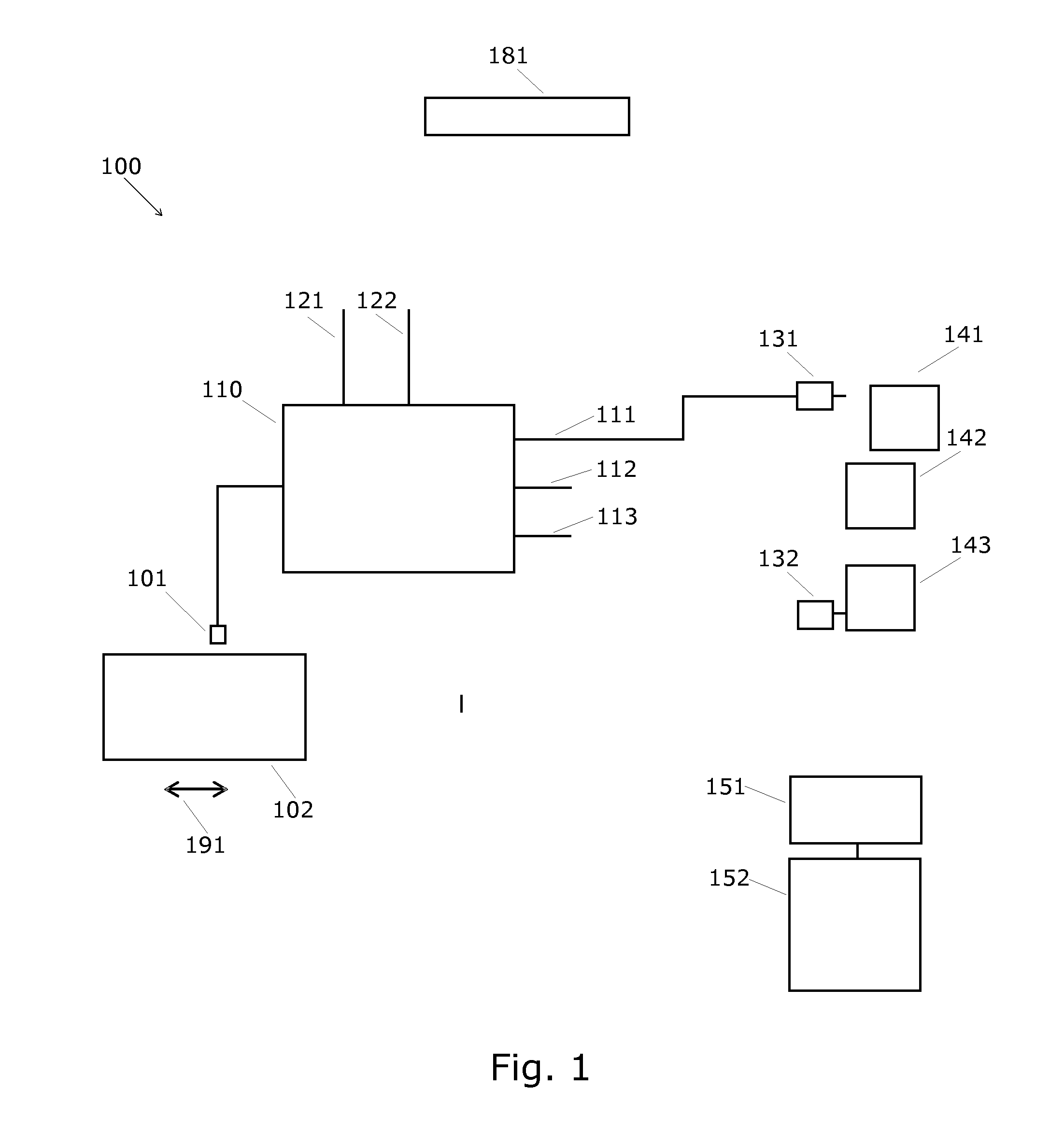
[0032]FIG. 1 shows an ambient control system 100 for use with a bed 102 of a patient scanner such as an MR scanner or other present or future scanners where the patient is located on a bed which is moveable relative to the scanner, e.g. along the longitudinal direction 191 of the patient lying on the bed 102.

[0033]The system comprises a bed sensor 101 which is capable of sensing the position of the bed or movement of the bed. For example the bed sensor may be an optical sensor capable of detecting one or more positions of the bed. For example, the bed may be provided with reflecting items which are detectable by the optical bed sensor. Mechanical contact sensors or other types of sensors, for example an encoder connected to the motor used for driving the bed may also be used.

[0034]The output of the bed sensor 101 is connected to an input of a controller 110. The controller 110 has one or more outputs 111-113 provided for supplying a control signal to one or more appliances 141-143 c...


PUM


Abstract

The invention relates to a system (100) for automating adjustment or adaptation of devices (141-143) such as light, computer programs and positioning of devices used during patient examination. The patient examination is performed by use of a scanner system where the patient is lying on a bed (102) which can be moved into a scanner zone of the scanner where the scanning can be performed and away from the scanner zone. The automated control is achieved by detecting the position of the bed and using the detected position for adjusting or adapting the state, i.e. the function or working of one or more devices (141-143).

Description

FIELD OF THE INVENTION[0001]The invention relates to a control system for controlling appliances, in particular to such a control system for use with a patient scanner.BACKGROUND OF THE INVENTION[0002]Patient examination by use of scanners such as MR, CT and ultrasound scanners involves different processes. During the examination various appliances such as computer screens may be used in different ways depending on the progress of the examination. Therefore, the clinical personnel may need to adjust the appliances, such as the location of the computer screen, during the examination. The adjustment of appliances may be time consuming and inconvenient for the examination.[0003]Accordingly, it is a problem that clinical personnel may not be able to focus fully on the examination itself, but may also need to perform adjustments and adaptations of various appliances used in the scanner room.[0004]U.S. Pat. No. 6,264,329 discloses a uniquely position adjustable ophthalmic instrument suppo...

Claims


Application Information

Patent Timeline
Patent Type & Authority Applications(United States)
IPC IPC(8): A61B6/04
CPCA61B6/0407H05B47/175
Inventor TAVANTI, MONICAZHAN G, YICHEN, NJIN-ZUELEVELT, AALDERT JANVAN ASBECK-METSELAAR, ANNEMARIE CHRISTIN YVONNE
Owner KONINKLJIJKE PHILIPS NV
Learn More