Control device of dental handpiece
a control device and handpiece technology, applied in dental tools, dental surgery, medical science, etc., can solve the problems of cutting tools becoming apt to be broken, and achieve the effects of reducing the load on the motor, preventing shock, and reducing the rotation torqu
- Summary
- Abstract
- Description
- Claims
- Application Information
AI Technical Summary
Benefits of technology
Problems solved by technology
Method used
Image

Examples
first embodiment
[0042]The present invention will be described below in detail on the basis of the embodiment shown in the attached drawings.
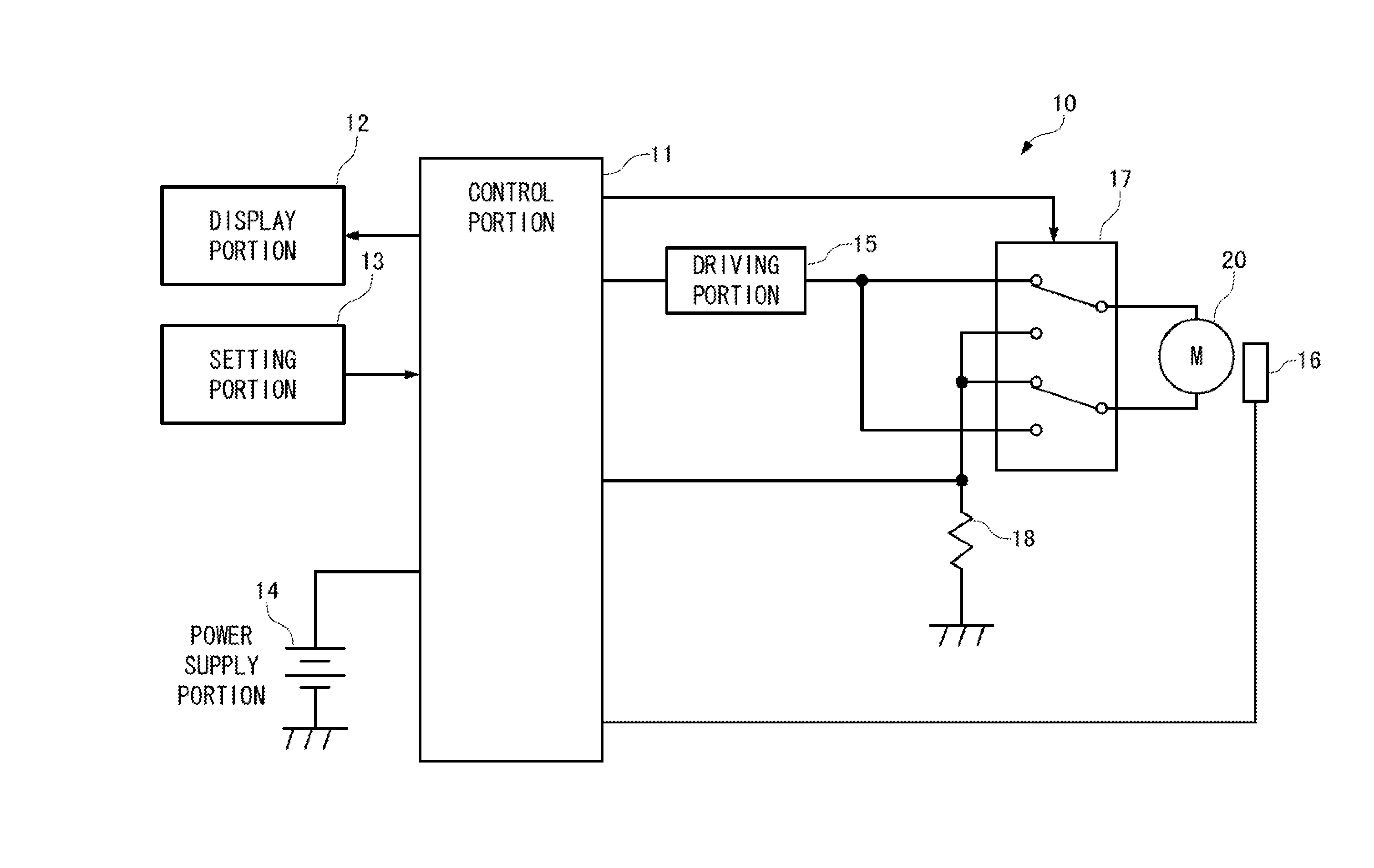
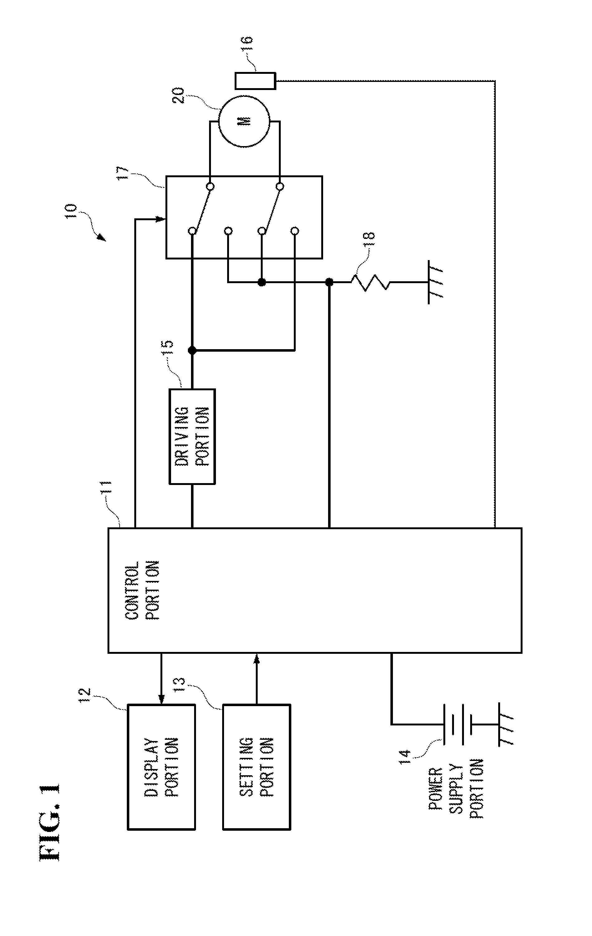
[0043]As shown in FIG. 1, a control device 10 of a dental handpiece (hereinafter, simply called as handpiece) is one for controlling the operation of a motor 20 built in the handpiece, and the control device 10 comprises a control portion 11, a display portion 12, a setting portion 13, a power supply portion 14, a driving portion (voltage application portion) 15, a sensor 16, a relay (rotational direction switching portion) 17, and a current detection resistor 18.
[0044]The control portion 11 denotes a computer unit provided with a CPU, a memory, and the like.
[0045]The display portion 12 denotes a monitor, which displays information indicating rotation speeds, arising torques, and the like as the operating state of a motor 20, information for carrying out the operation setting of the motor 20 at the control portion 11, and the like, an indicator lamp, and the li...
second embodiment
[0071]It is possible, as described in the first embodiment, to render each of the acceleration rate and the deceleration rate to be a fixed value in the control device 10 of a handpiece. However, for example, motors 20 each have an individual difference, and the individual difference varies depending on the period of usage of the control device 10 or the motor 20. Accordingly, there is a fear that it becomes not possible to adequately enjoy the effects of the present invention of being able to prevent a large rotation torque from being applied to the cutting tool at the time of reverse actuation of switching from forward rotation to reverse rotation (or the converse thereof) when the acceleration rate and deceleration rate of a fixed value are used. On the other hand, if the acceleration rate and deceleration rate are lessened, it becomes possible to prevent a large rotation torque from being applied to the cutting tool; however, it means to reduce cutting efficiency. On this accoun...
third embodiment
[0083]The control portion 11 can perform variable control of one of or both the acceleration rate and deceleration rate. An example of performing variable control of the acceleration rate and deceleration rate will be described in a third embodiment.
[0084]In FIGS. 6A, 6B, there is shown one example thereof, which is on the precondition that the set rotation speed of the motor 20 is variably controlled between R1 and R2, and the set application voltage is subjected to variable control in between V1 and V2 according to this set rotation speed. In the control portion 11 in this case, the relationship between the rotation speed and the application voltage of the motor 20 is stored. As shown in FIG. 7A, for example, it is assumed that the rotation speeds R1, R2 and the motor application voltages V1, V2 are in a proportional relationship (motor application voltage V=a×rotation speed R, a: proportionality constant). Incidentally, this relational expression is taken by causing the motor 20 ...
PUM
 Abstract
Description
Claims
Application Information
 - R&D
- Intellectual Property
- Life Sciences
- Materials
- Tech Scout
- Unparalleled Data Quality
- Higher Quality Content
- 60% Fewer Hallucinations
Browse by: Latest US Patents, China's latest patents, Technical Efficacy Thesaurus, Application Domain, Technology Topic, Popular Technical Reports.
© 2025 PatSnap. All rights reserved.Legal|Privacy policy|Modern Slavery Act Transparency Statement|Sitemap|About US| Contact US: help@patsnap.com