Drive arrangement for a bicycle, having a greater difference in the number of teeth between the largest and the smallest rear chain sprocket

Active Publication Date: 2014-05-08
SRAM
View PDF8 Cites 16 Cited by
  • Summary
  • Abstract
  • Description
  • Claims
  • Application Information

AI Technical Summary

Benefits of technology

The invention is about a shifting mechanism for bicycles that ensures smooth and reliable shifting between sprockets. The length of the chain section between the chain guide roller and the rear chain sprocket is important for preventing chain curvature and ensuring shifting between sprockets. The difference in the number of teeth between the rear sprockets can also affect the gear ranges and makes the drive arrangement suitable for uphill, level, and fast downhill riding.

Problems solved by technology

In this connection, a shifting process in which the drive chain is supposed to be shifted from an active sprocket to an inactive chain sprocket that is larger in diameter is particularly problematic, because the chain must rise from the currently active sprocket to the inactive chain sprocket having the larger diameter.

Method used


Image

  • Drive arrangement for a bicycle, having a greater difference in the number of teeth between the largest and the smallest rear chain sprocket
  • Drive arrangement for a bicycle, having a greater difference in the number of teeth between the largest and the smallest rear chain sprocket
  • Drive arrangement for a bicycle, having a greater difference in the number of teeth between the largest and the smallest rear chain sprocket

Examples


Embodiment Construction

[0043]In the following, reference will be made to FIGS. 1 to 7 jointly, for an explanation of the present invention. If individual figures are particularly suitable for a representation of the technical characteristics being described, at specific locations of the description, this will be separately emphasized.

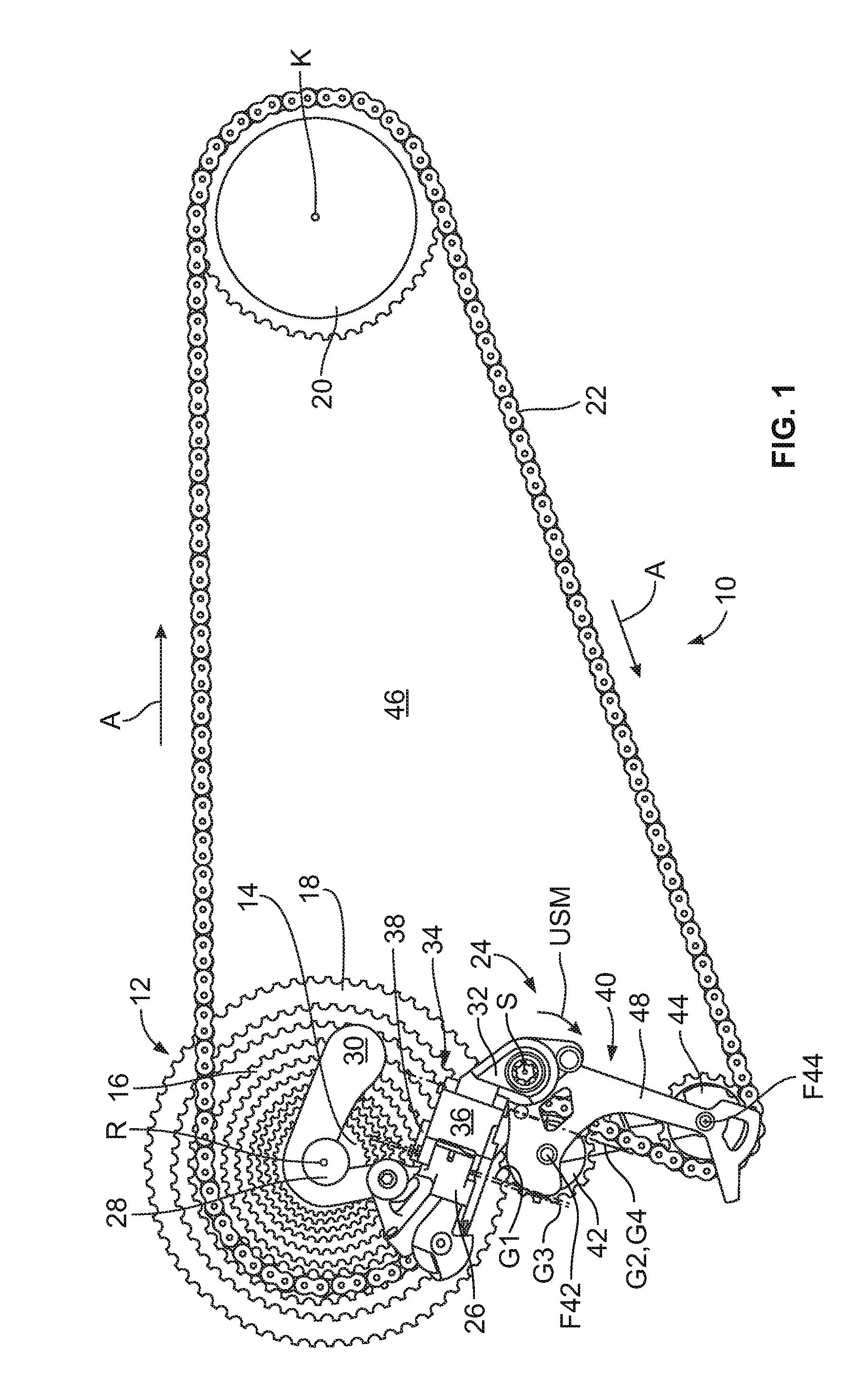
[0044]In the figures, an embodiment of a drive arrangement of the present application, according to the invention, is referred to in general as 10.

[0045]The drive arrangement 10 comprises an arrangement 12 of sprockets that are coaxial with reference to a sprocket axis R. Sprocket axis R is orthogonal to the plane of the drawing of FIG. 1. Only the sprocket having the smallest diameter is identified with the reference symbol 14, the sprocket selected to be active in FIG. 1 is identified with the reference symbol 16, and the sprocket having the largest diameter is identified with the reference symbol 18. In the example shown in the figures, the arrangement 12 of the coaxial re...


PUM


Abstract

A drive arrangement for a bicycle including a chainring having a chainring axis, a plurality of different rear sprockets, the plurality of rear sprockets sharing a sprocket axis, a drive chain that runs around the rear sprockets and the chainring and in meshing engagement with a selected active sprocket of the plurality of rear sprockets and the chainring, and a rear derailleur. The rear derailleur is configured to shift the chain over a plurality of sprockets having a difference in tooth count of over 25 teeth ranging from a smallest to a largest sprocket.

Description

BACKGROUND OF THE INVENTION[0001]A drive arrangement for a bicycle is known, for example, from U.S. Pat. No. 3,748,916. This known drive arrangement describes a rear chain guide. The rear chain guide has a chain guide roller that is disposed, with reference to an active sprocket, tangential to a next-larger inactive sprocket, in order to improve the shifting process. In the sense of the present application, a chain guide roller that is positioned by the chain guide closer to the sprocket is the chain guide roller off which the drive chain, rotating in the drive direction, last runs before it runs onto the active rear sprocket as viewed in the direction of the sprocket axis.BRIEF SUMMARY OF THE INVENTION[0002]The present invention relates to a drive arrangement for a bicycle. The drive arrangement includes a front chainring that can rotate about a chainring axis. A plurality of coaxial rear chain sprockets is provided having different diameters and different numbers of teeth. A drive...

Claims


Application Information

Patent Timeline
IPC IPC(8): B62M1/36F16H9/24
CPCF16H9/24B62M1/36B62M9/126B62M9/121B62M9/16B66C23/202B66C23/205
Inventor BOHM, ROBERT
Owner SRAM
Why Eureka
Try Eureka