
Air conditioner using cooling/dehumidifying energy recovery technology

Inactive Publication Date: 2014-04-17
AIRTECH +1
View PDF11 Cites 1 Cited by
  • Summary
  • Abstract
  • Description
  • Claims
  • Application Information

AI Technical Summary

Benefits of technology

The present invention provides an air conditioner with a heat exchanger at the front of the cooling coil to prevent cold draft and save energy by reheating the air. It also includes a damper to control the temperature and humidity of the air discharged to the indoor space and a vertical air passage to efficiently remove condensate and prevent cooling efficiency deterioration. The technical effects include prevention of cold draft, energy savings, precise control of air temperature and humidity, and improved cooling efficiency.

Problems solved by technology

If the cooled air is directly discharged to the body of a user, the user may feel displeasure, i.e., cold draft.
In case of a rainy day in which the humidity in the air is high, it is impossible to sufficiently perform dehumidifying, and also it is difficult to control the temperature and humidity at the same time.
In a conventional air conditioner, since the cooled air discharged from the cooling coil forms an ascending air current, the condensate formed on the surface of the cooling coil cannot be naturally fallen down by gravity but stays thereon due to drawing force of the fan, and thus the surface of the cooling coil is wet and cooling efficiency of the cooling coil is deteriorated.

Method used


Image

  • Air conditioner using cooling/dehumidifying energy recovery technology
  • Air conditioner using cooling/dehumidifying energy recovery technology
  • Air conditioner using cooling/dehumidifying energy recovery technology

Examples


first embodiment

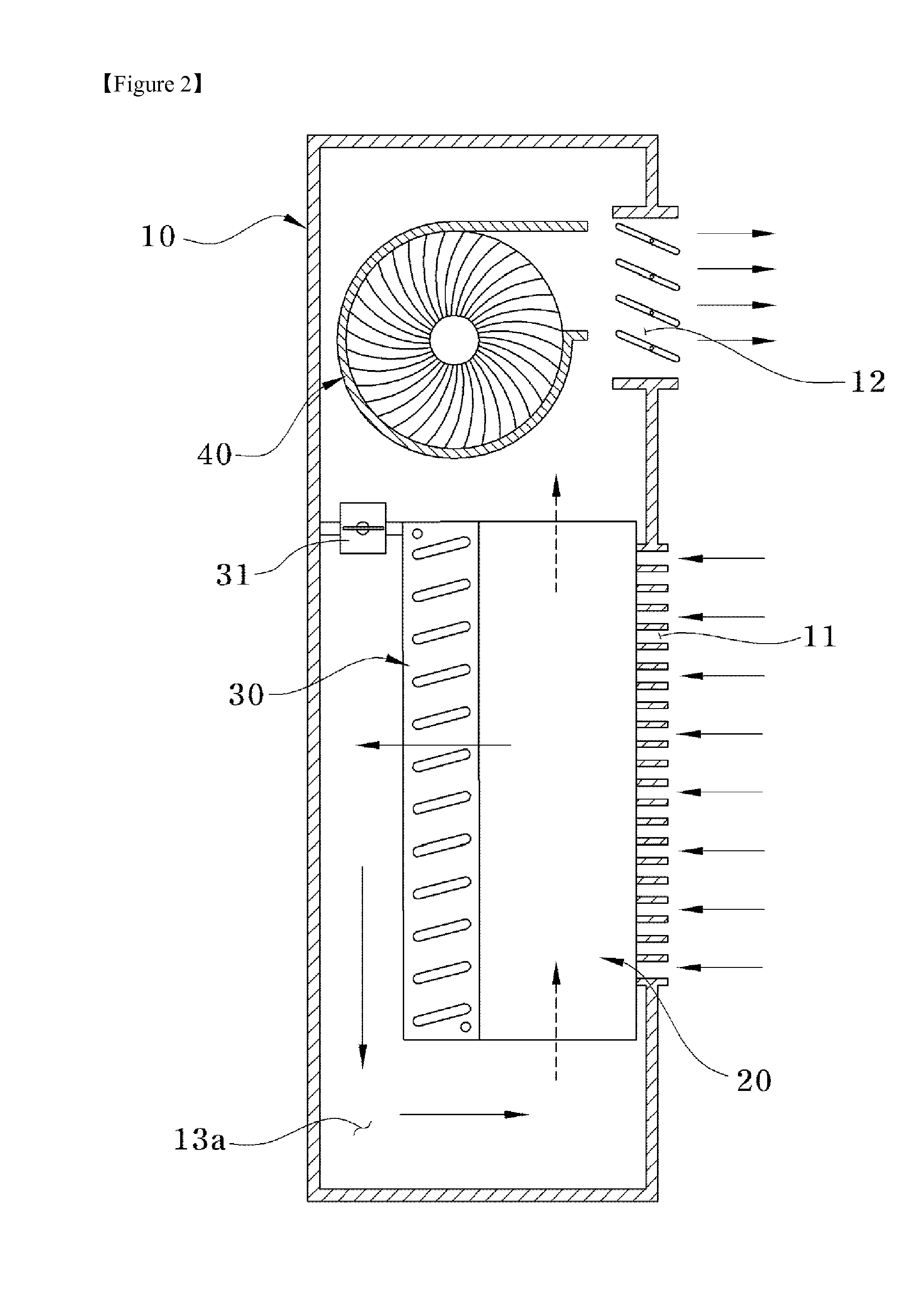
[0024]In a first embodiment, as shown in FIG. 2, all of the intake hole 11 and discharge hole 12 are formed in the front surface of the main body 10, and the heat exchanger 20 and cooling coil 30 are disposed, in turn, downstream from the intake hole 11, and a separate air passage 13a is provided downstream of the cooling coil 30.

[0025]The heat exchanger 20 disposed downstream from the intake hole 11 performs heat exchange between air introduced into the main body 10 and cooled air, such that the introduced air is previously cooled, thereby ultimately enhancing cooling efficiency. As shown in FIG. 3, the heat exchanger 20 is a stacked plate type heat exchanger in which plate type first and second heat exchanging plates 20A and 20B are alternately stacked. Heat exchanger intake and discharge holes 21A, 21B, 22A, 22B are formed in each of the first and second heat exchangers 20A, 20B so that air passing through the heat exchanger 20 is cross-flowed.

[0026]In other words, as shown in FI...

second embodiment

[0038]As shown in FIG. 4, a second embodiment relates to an air conditioner in which the intake hole 11 for sucking the indoor air is formed in the rear surface of the main body 10, and the discharge hole 12 for discharging the cooled air to the indoor space is formed in the front surface of the main body 10. Therefore, the second embodiment is the same as the first embodiment except that installation positions of the heat exchanger 20, cooling coil 30 and air passage 13b are opposed to those in the first embodiment. That is, in the second embodiment, the intake hole 11 is formed in the rear surface of the main body 10, and the heat exchanger 20 and cooling coil 30 are disposed, in turn, downstream from the intake hole 11, and the air passage is formed between the front surface of the main body 10 and the cooling coil 30 and also at the lower side of the heat exchanger 20, and thus a reversed “L”-shaped air passage 13b is formed. Further, a damper 31 may be further provided at an up...

third embodiment

[0041]As shown in FIG. 6, a third embodiment relates to an air conditioner in which the intake hole 11 is formed in both side surfaces of the main body 10. Except that, unlike the first embodiment, the intake hole 11 is formed in the side surfaces of the main body 10, the rest configuration, i.e., the heat exchanger 20, cooling coil 30 and air passage 13c of the third embodiment are the same as those of the first embodiment. As described above, if the intake hole 11 is formed in the side surfaces of the main body 10, it is prevented that the cooled air is introduced again into the main body 10 through the intake hole 11 due to the drawing force of the fan while the cooled air is discharged through the discharge hole 12.


PUM


Abstract

The present invention relates to an air conditioner. The air conditioner includes: a main body 10 having an intake hole 11 and a discharge hole 12; a heat exchanger 20 disposed within the main body 10 and installed downstream from the intake hole 11; a cooling coil 30 disposed within the main body 10 and installed downstream from the heat exchanger 20; a fan 40 disposed within the main body 10 and installed downstream from the cooling coil 30 to exhaust air within the main body 10 to an indoor space; and air passages 13a, 13b, 13c and 13d for introducing air passing through the cooling coil 30 again into the heat exchanger 20. Thus, according to the present invention, cooling / dehumidifying energy may be recovered from cooled air to prevent a cold draft from occurring and improve energy usage efficiency.

Description

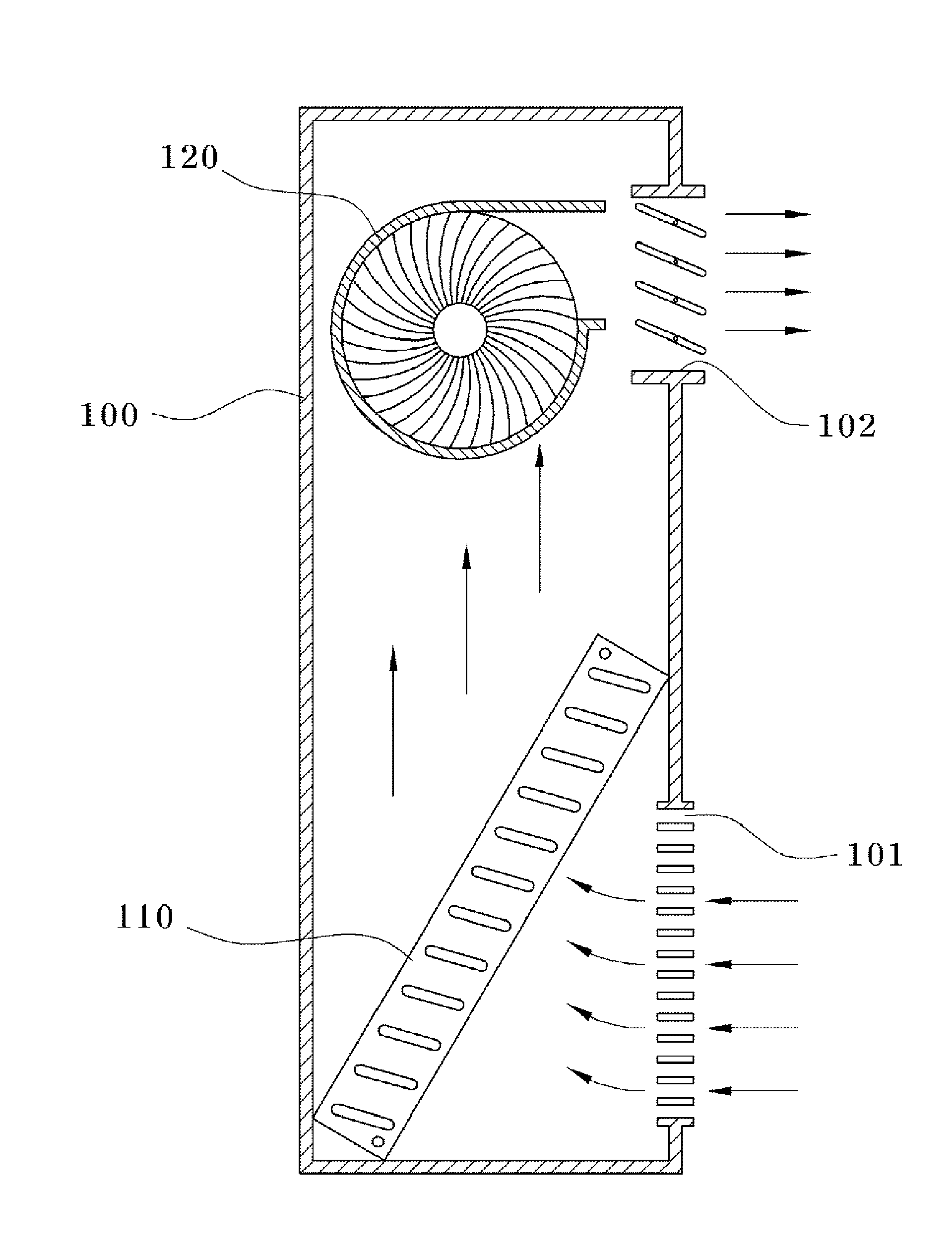
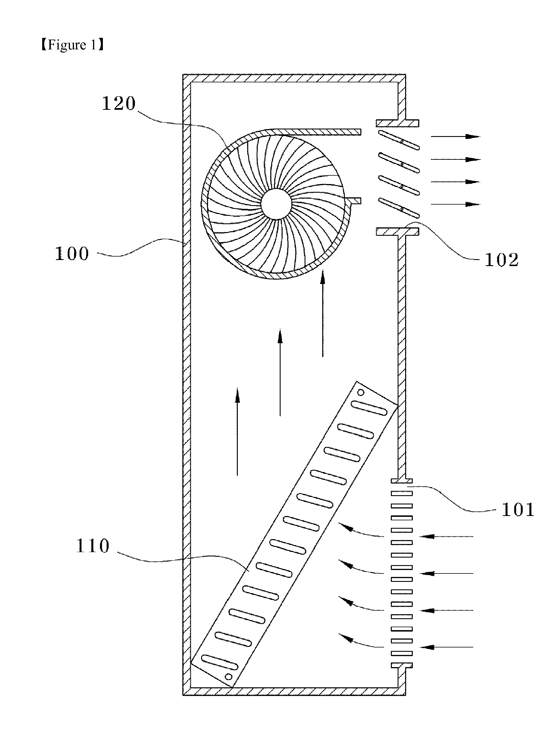
TECHNICAL FIELD[0001]The present invention relates to an air conditioner using cooling / dehumidifying energy recovery technology, and particularly, to an air conditioner using cooling / dehumidifying energy recovery technology, in which a heat exchanger is provided in order to recover the cooling / dehumidifying energy.BACKGROUND ART[0002]In general, an air conditioner for air-conditioning an indoor space in the summer includes an indoor unit and an outdoor unit. As shown in FIG. 1, an intake hole 101, a cooling coil 110, a fan 120 and a discharge hole 102 are provided in the indoor unit. Herein, indoor air is sucked through the intake hole 101 formed at the lower portion of the indoor unit 100, passed through the cooling coil 110 so as to be cooled and then supplied to an indoor space through the discharge hole 102 formed at the upper portion of the indoor unit 100 by using a blower or the fan 120.[0003]Herein, the air introduced into the indoor unit through the intake hole 101 is coole...

Claims


Application Information

Patent Timeline
IPC IPC(8): F25D21/04F24F1/0083F24F1/0323
CPCF25D21/04F24F13/30F24F1/0323F24F1/0083F24F3/14F24F1/00F24F12/00
Inventor YOO, SEONGYEONYOON, HONGIK
Owner AIRTECH
Learn More