
Modular wall nesting system

Active Publication Date: 2014-04-17
ICE EDGE BUSINESS SOLUTIONS
View PDF10 Cites 23 Cited by
  • Summary
  • Abstract
  • Description
  • Claims
  • Application Information

AI Technical Summary

Benefits of technology

The present invention provides systems, methods, and apparatus for nested window frames and other objects in modular wall panels. The technical effects include quick and easy assembly, disassembly, and reconfiguration of nested wall modules with great ease. The nested wall modules can include one or more center-mounted panels nested within face-mounted panels, face-mounted panels nested within a center-mounted panel, passthroughs, openings, shadow boxes, or other objects nested within a modular wall panel. The invention allows for easy and flexible secure mounting options in different environments.

Problems solved by technology

Office space can be relatively expensive be due to the basic costs of the location
and size of the office space.
In addition to these costs, an organization may incur further expense configuring the office space in a desirable layout.
While conventional modular wall systems can provide various advantages, such as those described above, conventional modular wall systems are limited in design choices.
For example, many conventional modular wall systems do not allow for inclusion of windows or other objects within a panel.
Other conventional modular wall systems may allow for windows or other objects within a panel, typically do not provide much functional or aesthetic variability without complicated or time consuming installation procedures.
Accordingly, there are a number of disadvantages with conventional solid wall systems that can be addressed.

Method used


Image

  • Modular wall nesting system
  • Modular wall nesting system
  • Modular wall nesting system

Examples


Embodiment Construction

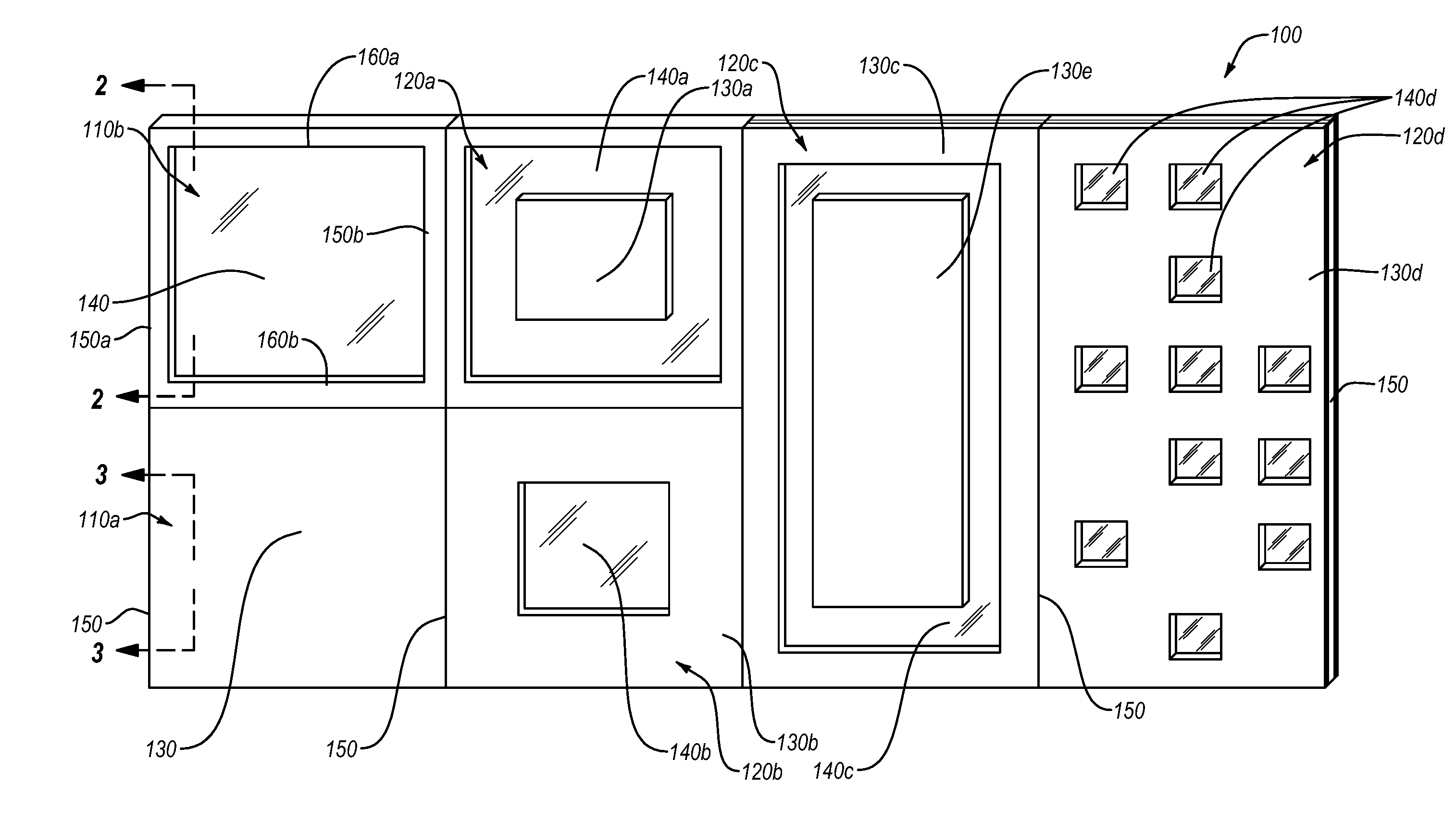
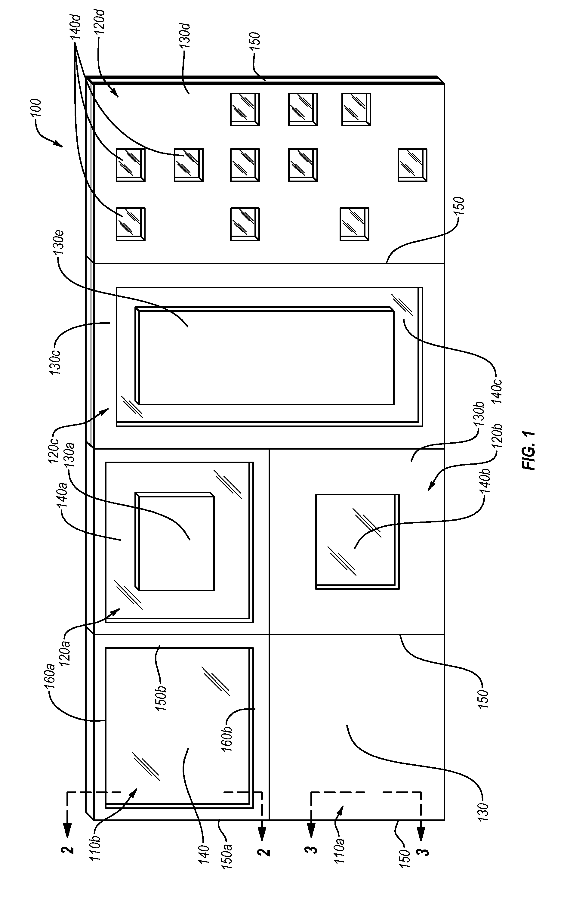
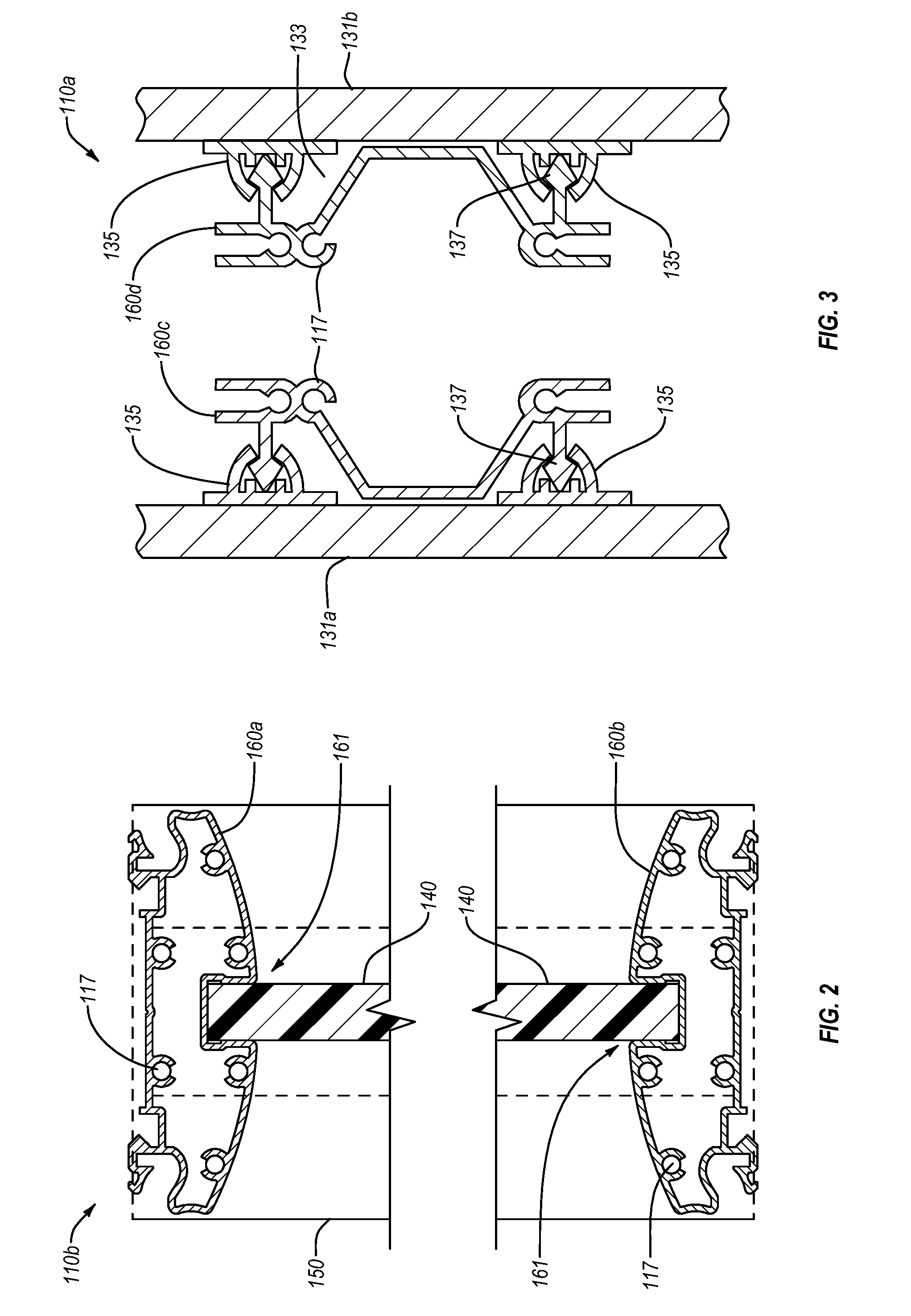
[0028]Implementations of the present invention provide systems, methods, and apparatus for nesting windows, other panels, passthroughs, or other objects into module wall panels to form nested wall modules. For instance, the nested wall modules can include one or more center-mounted panels nested within face-mounted panels. In such systems, the center-mounted panel can form a window within the face-mounted panels. In additional implementations, the nested wall modules can include face-mounted panels nested within a center-mounted panel. Still further implementations, can include passthroughs, openings, shadow boxes, or other objects nested within a modular wall panel. Furthermore, these systems and components enable quick and efficient assembly, disassembly, and reconfiguration of nested wall modules with great ease. Accordingly, implementations of the present invention can be easily adapted to the environment of use and provide a number of secure mounting options.

[0029]In one or mor...


PUM


Abstract

Implementations of the present invention relate to systems, methods, and apparatus for incorporating face- and center-mounted panels into a single wall module to form nested wall modules. For instance, face-mounted panels can nest within the center-mounted panels. Additionally or alternatively, center-mounted panels can nest within the face-mounted panels to form windows.

Description

CROSS-REFERENCE TO RELATED APPLICATIONS[0001]This application is a 35 U.S.C. §371 National Stage of PCT / US12 / 41906, filed on Jun. 11, 2012, entitled “Modular Wall Nesting System,” which claims priority to U.S. Provisional Patent Application No. 61 / 495,974, filed on Jun. 11, 2011. The entire content of each of the afore-mentioned patent applications is incorporated by reference herein.BACKGROUND OF THE INVENTION[0002]1. The Field of the Invention[0003]invention generally relates to modular wall systems. More specifically, the present invention relates to apparatus, systems, and methods for nesting windows, other panels, passthroughs, or other objects into module wall panels.[0004]2. Background and Relevant Art[0005]Office space can be relatively expensive be due to the basic costs of the location[0006]and size of the office space. In addition to these costs, an organization may incur further expense configuring the office space in a desirable layout. An organization might purchase or...

Claims


Application Information

Patent Timeline
IPC IPC(8): E04B2/74E04B2/72E04C2/38
CPCE04B2/7453E04B2/721E04C2/38E04B2/745E04B2002/7483E04B2/7435E04B2/7422E04B2/7424
Inventor GOSLING, GEOFFSMED, MOGENS
Owner ICE EDGE BUSINESS SOLUTIONS
Learn More