
Joint support device

a support device and joint technology, applied in the field of joint support devices, can solve the problems of ineffective day elastic knee braces, inconvenient use of braces during sports, and the majority of knee injuries

Active Publication Date: 2014-04-10
CHANDLER JR FRANKLIN WOODROW
View PDF10 Cites 13 Cited by
  • Summary
  • Abstract
  • Description
  • Claims
  • Application Information

AI Technical Summary

Benefits of technology

The present invention is a joint support device comprising two layers of tubular layers that are spirally wound together. The first tubular layer has crisscrossing fibers that spiral from the bottom to the top, while the second tubular layer has crisscrossing fibers that spiral in the opposite direction. This design provides improved strength and stability of the joint support device. The method of making the joint support device involves suspending each tubular layer on a cylinder and twisting them in opposite directions to create the spiral. The technical effect of this invention is that it provides a stronger and more stable joint support device for various applications such as construction, manufacturing, and sports equipment.

Problems solved by technology

The twisting and rotation of the wearer's knee causes a majority of knee injury in athletics.
Steel or other action limiting knee braces limit athletic performance to a degree so that the braces cannot be used comfortably during sports.
Further, the present day elastic knee braces are ineffective and therefore are generally not used as well.

Method used


Image

  • Joint support device
  • Joint support device
  • Joint support device

Examples


Embodiment Construction

[0017]The following detailed description is of the best currently contemplated modes of carrying out exemplary embodiments of the invention. The description is not to be taken in a limiting sense, but is made merely for the purpose of illustrating the general principles of the invention, since the scope of the invention is best defined by the appended claims.

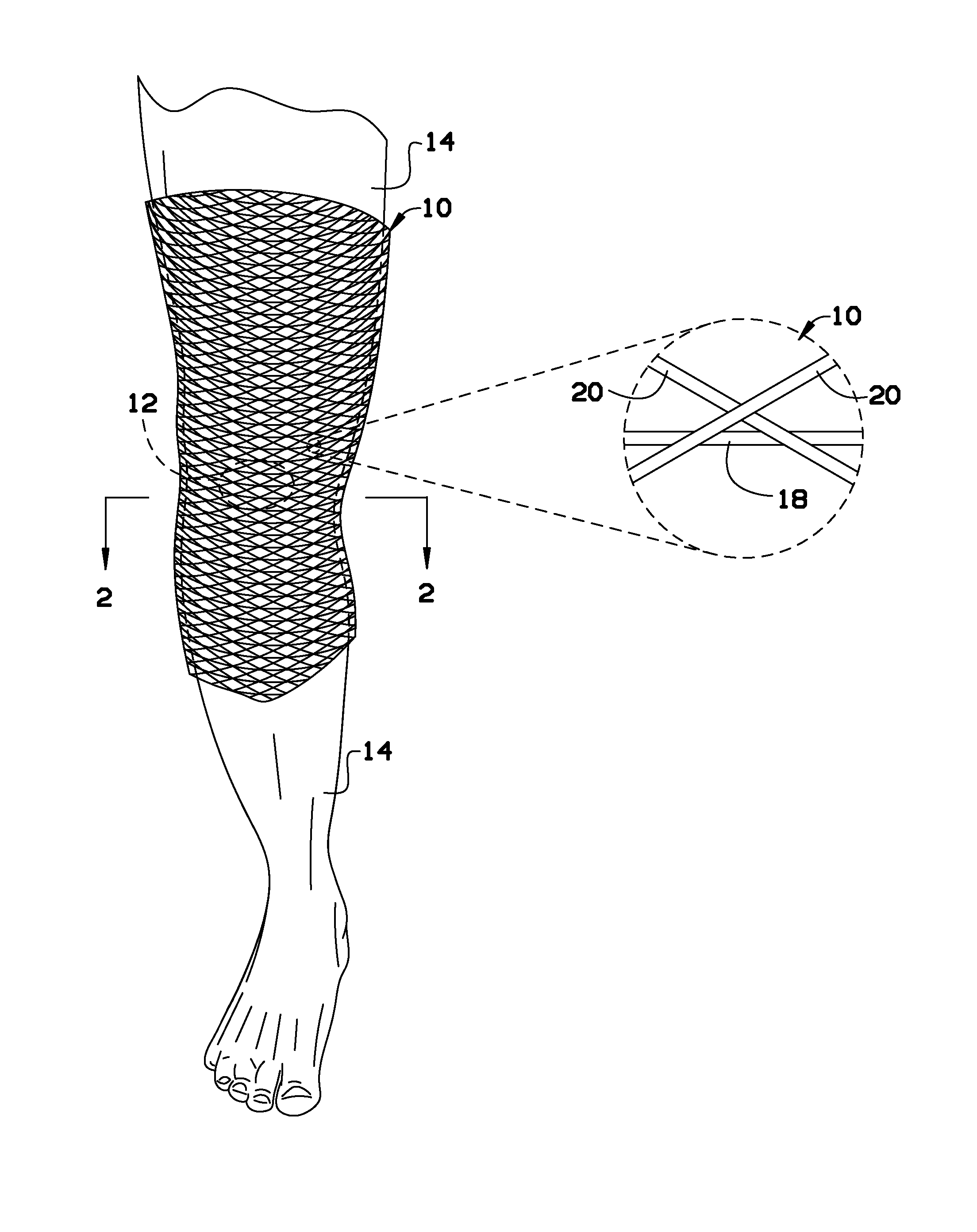
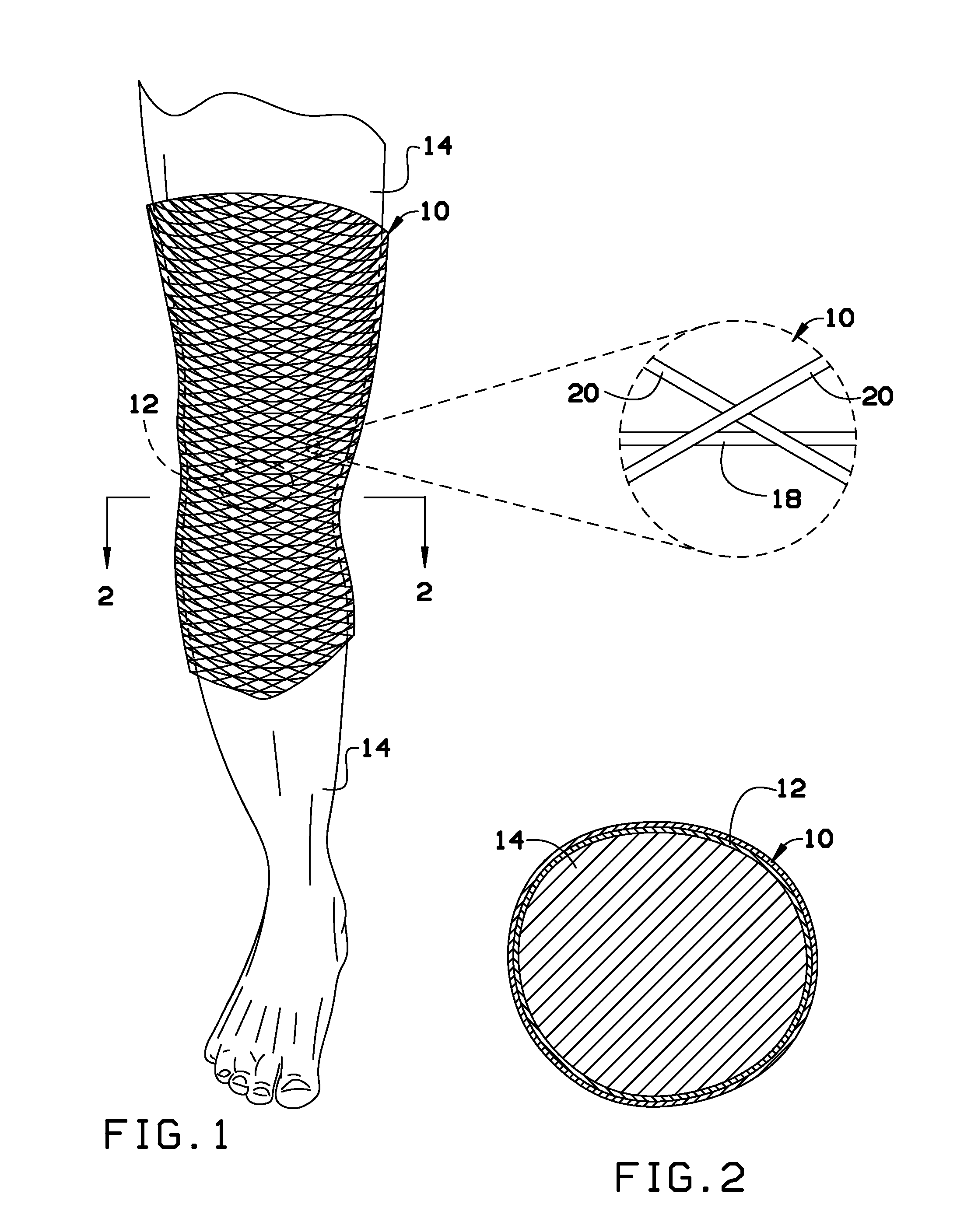
[0018]Broadly, an embodiment of the present invention provides a joint support device. The joint support device may include a first tubular layer and a second tubular layer both made of crisscrossing fibers. The crisscrossing fibers of the first tubular layer may be oriented in a spiral in a first direction and the crisscrossing fibers of the second tubular layer may be oriented in a spiral in an opposite direction of the first direction. The first and second tubular layers may be layered together and may be attached to an existing elastic knee brace.

[0019]The present invention may include a joint support device such as a knee s...


PUM


Abstract

A joint support device is provided. The joint support device may include a first tubular layer and a second tubular layer both made of crisscrossing fibers. The crisscrossing fibers of the first tubular layer may be oriented in a spiral in a first direction and the crisscrossing fibers of the second tubular layer may be oriented in a spiral in an opposite direction of the first direction. The first and second tubular layers may be layered together and may be attached to an existing elastic knee brace.

Description

CROSS-REFERENCE TO RELATED APPLICATION[0001]This application claims the benefit of priority of U.S. provisional application No. 61 / 709,744, filed Oct. 4, 2012, the contents of which are herein incorporated by reference.BACKGROUND OF THE INVENTION[0002]The present invention relates to a joint support device and, more particularly, to a joint support device that may attach to an elastic knee brace.[0003]A knee orthosis (KO) or knee brace is a brace that extends above and below the knee joint and is generally worn to support or align the knee. In the case of diseases causing neurological or muscular impairment of muscles surrounding the knee, a KO can prevent flexion or extension instability of the knee. In the case of conditions affecting the ligaments or cartilage of the knee, a KO can provide stabilization to the knee by replacing the function of these injured or damaged parts. For instance, knee braces can be used to relieve pressure from the part of the knee joint affected by dise...

Claims


Application Information

Patent Timeline
Patent Type & Authority Applications(United States)
IPC IPC(8): A61F5/01D04H3/05
CPCD04H3/05A61F5/0123A61F5/0109
Inventor CHANDLER, JR., FRANKLIN WOODROW
Owner CHANDLER JR FRANKLIN WOODROW
Learn More