
Pilot operated relief valve with dual pilot regulators

a pilot regulator and relief valve technology, applied in the field of relief valves, can solve the problems of prone to leakage, heavy weight, and large manifold of multiple pressure relief valves

Active Publication Date: 2014-04-03
EMERSON PROCESS MANAGEMENT REGULATOR TECH INC
View PDF24 Cites 13 Cited by
  • Summary
  • Abstract
  • Description
  • Claims
  • Application Information

AI Technical Summary

Benefits of technology

This patent describes a pilot-operated relief valve which is designed to control fluid flow in a system. The valve has a plug that is moved by an actuator, which is in turn controlled by a pilot assembly. The pilot assembly includes two pilot valves that work together to relieve pressure on the actuator. When there is too much pressure, one of the pilot valves activates to allow fluid to flow through the valve. Overall, this design helps to control fluid flow and prevent damage to the system.

Problems solved by technology

Multiple pressure relief valve manifolds are typically large, heavy, and prone to leakage at the connection between the pressure relief valves and the manifold.

Method used


Image

  • Pilot operated relief valve with dual pilot regulators
  • Pilot operated relief valve with dual pilot regulators
  • Pilot operated relief valve with dual pilot regulators

Examples


Embodiment Construction

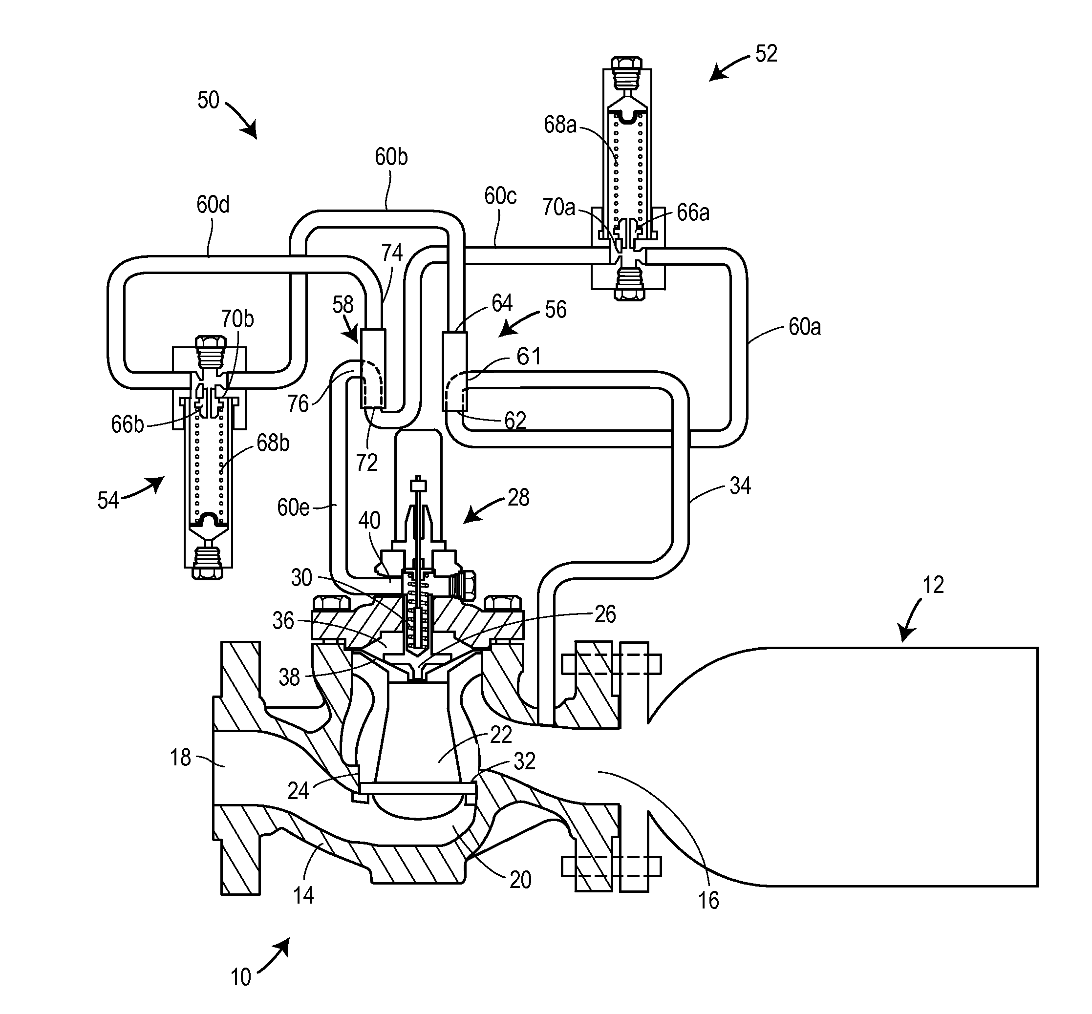
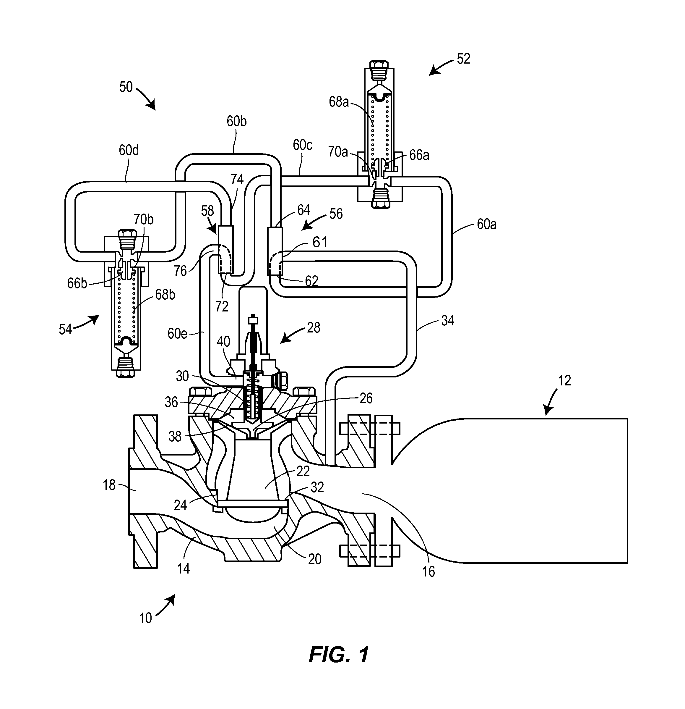
[0016]Referring now to the drawings and with specific reference to FIG. 1, a pilot operated relief valve 10 is fluidly connected to a fluid container 12. The pilot operated relief valve 10 includes a valve body 14 having a fluid inlet 16 and a fluid outlet 18 connected by a fluid passageway 20. A valve plug 22 and a valve seat 24 are disposed within the valve body 14. The valve plug 22 and the valve seat 24 cooperate to control fluid flow through the fluid passageway 20.

[0017]The valve plug 22 may be operatively connected to a stem 26 that is connected to a loading chamber 36 of an actuator 28. The actuator 28 may include biasing device, such as a spring 30, which biases the stem 26 and the valve plug 22 in a direction that moves a seating surface 32 of the valve plug 22 towards the valve seat 24 so that fluid flow through the fluid passageway 20 is normally prevented. When fluid pressure within the container 12 and thus within the inlet 16, exceeds a predetermined level, a loading ...


PUM


Abstract

A pilot operated pressure relief valve includes a valve body having a fluid inlet and a fluid outlet connected by a fluid passageway. A valve plug may be disposed within the fluid passageway, the valve plug cooperating with a valve seat to control fluid flow through the fluid passageway. An actuator may be connected to the valve plug, the regulator biasing the valve plug towards the valve seat. A pilot assembly may include a first pilot valve and a second pilot valve, wherein the pilot assembly directs fluid pressure upstream of the valve plug to one of the first and second pilot valves. When the upstream fluid pressure exceeds a predetermined level, the valve plug moves away from the valve seat allowing fluid to flow through the fluid passageway.

Description

FIELD OF THE DISCLOSURE[0001]The disclosure generally relates to relief valves and more specifically to pilot operated relief valves.BACKGROUND OF THE DISCLOSURE[0002]Pressure relief valves are used in a variety of commercial, industrial and domestic applications to maintain a pressure within a container below a predetermined maximum pressure. Specifically, if the pressure within the container exceeds a start-to-discharge pressure or predetermined maximum pressure, the pressure relief valve will vent a fluid or vapor to the atmosphere until the pressure within the container decreases below the predetermined maximum pressure. The amount and rate at which the fluid or vapor is vented to the atmosphere is associated with the magnitude of the pressure within the container.[0003]Different pressure relief valves have different sizes, start-to-discharge pressures and flow capacities. A pressure relief valve may be selected for use with a container based on a design specification of the con...

Claims


Application Information

Patent Timeline
Patent Type & Authority Applications(United States)
IPC IPC(8): F16K17/00
CPCF16K17/00F16K17/10Y10T137/7768
Inventor DIAZ, JUAN M.NASHERI, KHASHAYAR A.STEGER, BRYAN J.
Owner EMERSON PROCESS MANAGEMENT REGULATOR TECH INC
Learn More