
Display panel

a display panel and panel technology, applied in non-linear optics, instruments, optics, etc., can solve the problems of color shift or insufficient color saturation, insufficient vividness of the image observed by the viewer, etc., to improve the display quality of the display panel and correct the color shift of the image

Inactive Publication Date: 2014-03-27
AU OPTRONICS CORP
View PDF4 Cites 4 Cited by
  • Summary
  • Abstract
  • Description
  • Claims
  • Application Information

AI Technical Summary

Benefits of technology

The patent text discusses a method to improve the quality of display panels by adjusting the gaps between pixels in the sub-pixels. By doing so, the color shifting that occurs when viewing an image at a side angle can be corrected, resulting in a better display quality.

Problems solved by technology

In a conventional vertically arranged type LCD panel that is subject to the optical properties of liquid crystal molecules, the issue of color shift or insufficient color saturation may occur when a viewer watches the LCD panel at different viewing angles.
Although various solutions to the issue of color shift or insufficient color saturation have been proposed to solve the color washout problem, these solutions may bring about another color shift problem, i.e., when an image is viewed at a front angle and at a side angle, the image viewed at the side angle may be bluish, greenish, or a reddish in comparison with the image viewed at the front angle, and thereby the color of the image observed by the viewer is not vivid enough.

Method used


Image

  • Display panel
  • Display panel
  • Display panel

Examples


Embodiment Construction

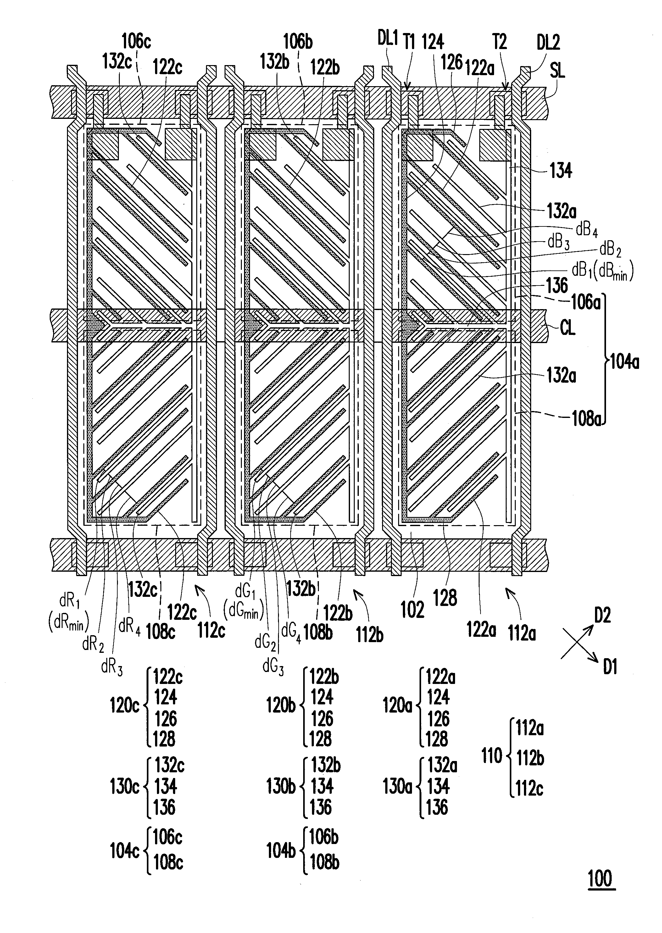
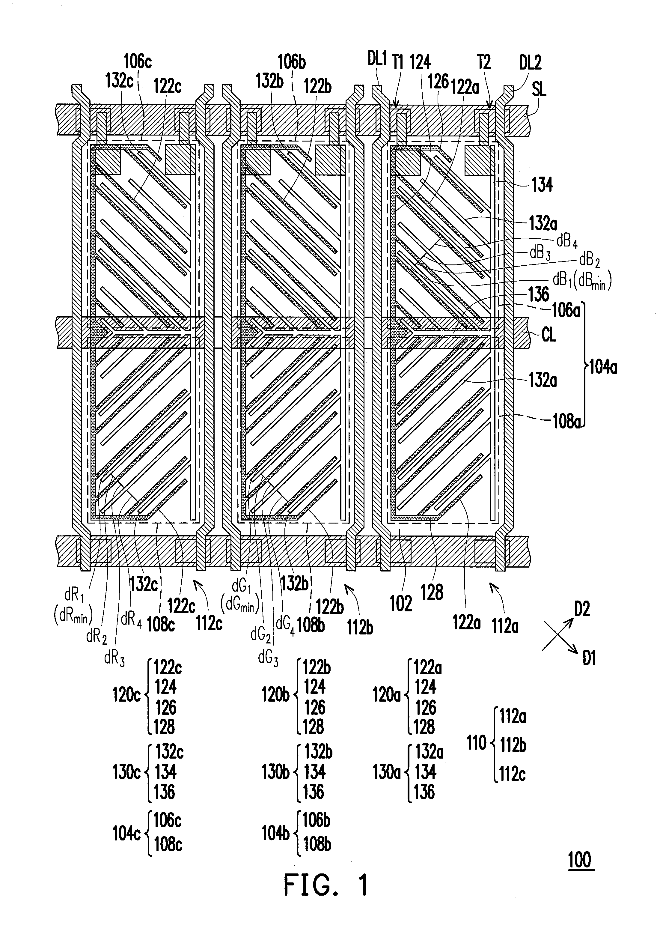
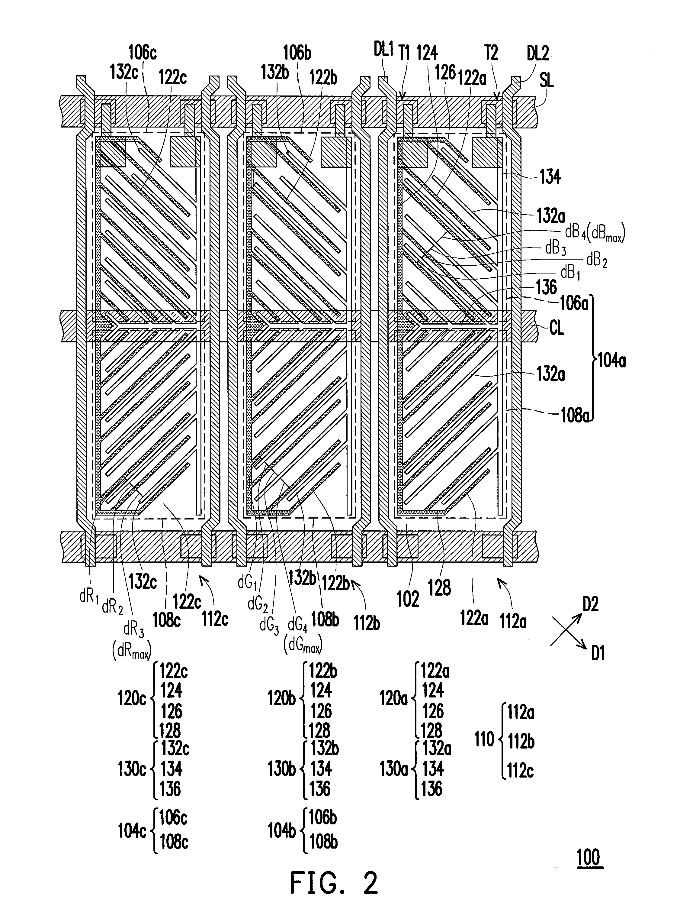
[0016]FIG. 1 is a schematic top view illustrating a display panel according to an embodiment of the invention. With reference to FIG. 1, the display panel 100 includes a substrate 102 and a pixel structure 110. The substrate 102 includes a first sub-pixel area 104a, a second sub-pixel area 104b, and a third sub-pixel area 104c, for instance. The pixel structure 110 is disposed on the substrate 102 and includes a first sub-pixel 112a, a second sub-pixel 112b, and a third sub-pixel 112c. In general, the display panel 100 further includes a color filter array (not shown) that includes a first color filter pattern, a second color filter pattern, and a third color filter pattern. The pixel structure 110 and the color filter array are correspondingly arranged. For instance, the first sub-pixel 112a and the first color filter pattern are correspondingly arranged, the second sub-pixel 112b and the second color filter pattern are correspondingly arranged, and the third sub-pixel 112c and the...


PUM

PropertyMeasurementUnit
sizeaaaaaaaaaa
sizeaaaaaaaaaa
areaaaaaaaaaaa

Abstract

A display panel includes a pixel structure that has first, second, and third sub-pixels. In the first sub-pixel, a first pixel electrode having first branches and a second pixel electrode having second branches are alternately arranged. Gap dB is defined between adjacent first and second branches. In the second sub-pixel, a third pixel electrode having third branches and a fourth pixel electrode having fourth branches are alternately arranged. Gap dG is defined between adjacent third and fourth branches. In the third sub-pixel, a fifth pixel electrode having fifth branches and a sixth pixel electrode having sixth branches are alternately arranged. Gap dR is defined between adjacent fifth and sixth branches. The gaps dB, dG, and dR at least include minimum gaps dBmin, dGmin, and dRmin and gaps dBn, dGn, and dRn, respectively. Here, dGn is equal to dRn, and (1 / dBn)≧[(1 / dRn)*1.1].

Description

CROSS-REFERENCE TO RELATED APPLICATION[0001]This application claims the priority benefit of Taiwan application serial no. 101135353, filed on Sep. 26, 2012. The entirety of the above-mentioned patent application is hereby incorporated by reference herein and made a part of this specification.BACKGROUND OF THE INVENTION[0002]1. Field of the Invention[0003]The invention relates to a panel. More particularly, the invention relates to a display panel.[0004]2. Description of Related Art[0005]Nowadays, the market demands a liquid crystal display (LCD) panel to develop its functions of high contrast ratio, no gray scale inversion, little color shift, high luminance, full color, high color saturation, fast response, wide viewing angle, etc. Currently, the technologies capable of fulfilling the wide-viewing-angle demand include a twist nematic (TN) LCD panel with a wide viewing film, an in-plane switching (IPS) LCD panel, a fringe field switching (FFS) LCD panel, a multi-domain vertically al...

Claims


Application Information

Patent Timeline
Patent Type & Authority Applications(United States)
IPC IPC(8): G02F1/1343
CPCG02F1/134309G02F1/134363
Inventor LU, MEI-JUCHEN, CHO-YANCHEN, KUAN-YUTSAO, SAU-WENKUNG, YEN-YINGTING, TIEN-LUN
Owner AU OPTRONICS CORP
Learn More