
Precision overprinting method of printed electronics rotary printing where location can be adjusted in real time

a technology of electronic rotary printing and overprinting precision, which is applied in the direction of printing presses, printing presses, rotary intaglio printing presses, etc., can solve the problems of insufficient overprinting precision, difficult accurate arrangement, and insufficient precision of one rotation-one register mark methods, etc., to achieve high precision ccd, easy identification, and precise image

Active Publication Date: 2014-03-27
KOREA INST OF MACHINERY & MATERIALS
View PDF10 Cites 14 Cited by
  • Summary
  • Abstract
  • Description
  • Claims
  • Application Information

AI Technical Summary

Benefits of technology

The camera device described in this patent allows for precise overprinting of micrometer size images using a high-precision camera sensor and a camera lens that compensates for pixel size. The device also includes a lamp to provide a clear image. By using different register marks and alignment methods, the device overcomes an alignment limit in a several tens of micrometer level. The technical effect is higher alignment precision through a fine shift adjustment.

Problems solved by technology

The correction method may be sufficient in image printing pursuing high-speed printing, but its precision is considerably insufficient in roll-to-roll rotary printing of an electronic element requiring a micrometer unit precision overprinting.
The reason why an overprinting precision in the one rotation-one register mark method is insufficient is that a location and a size of a printing line is changed in a micrometer level due to expansion and contraction of a film caused by various stress changes, such as printing pressure, dry heating, tension, and friction, which are inevitably applied while a thin roll printing film passes a plurality of printing units.
Thus, in the one register mark per rotation method, an accurate arrangement is difficult even when complex prediction calculations and methods are utilized.

Method used

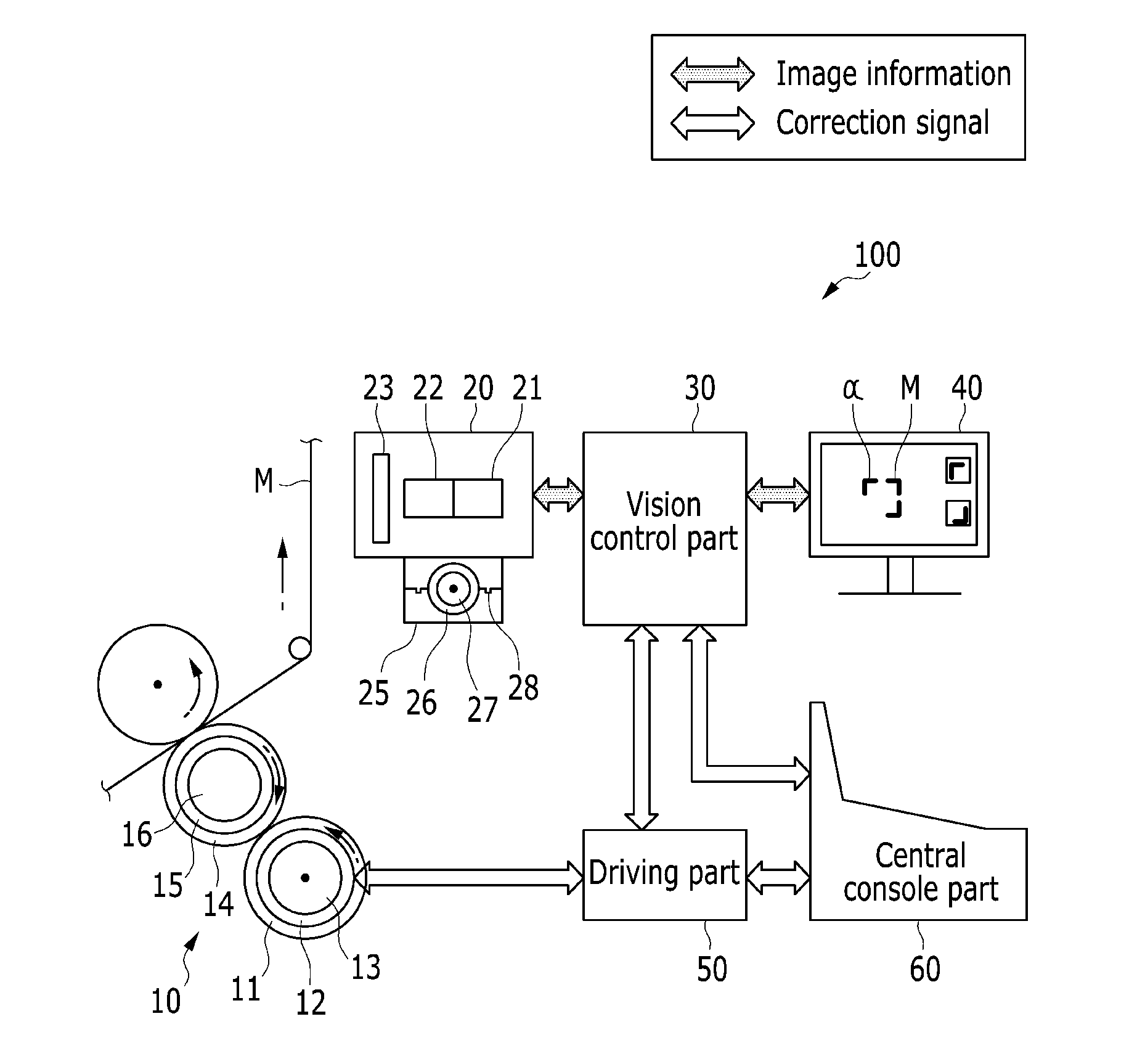
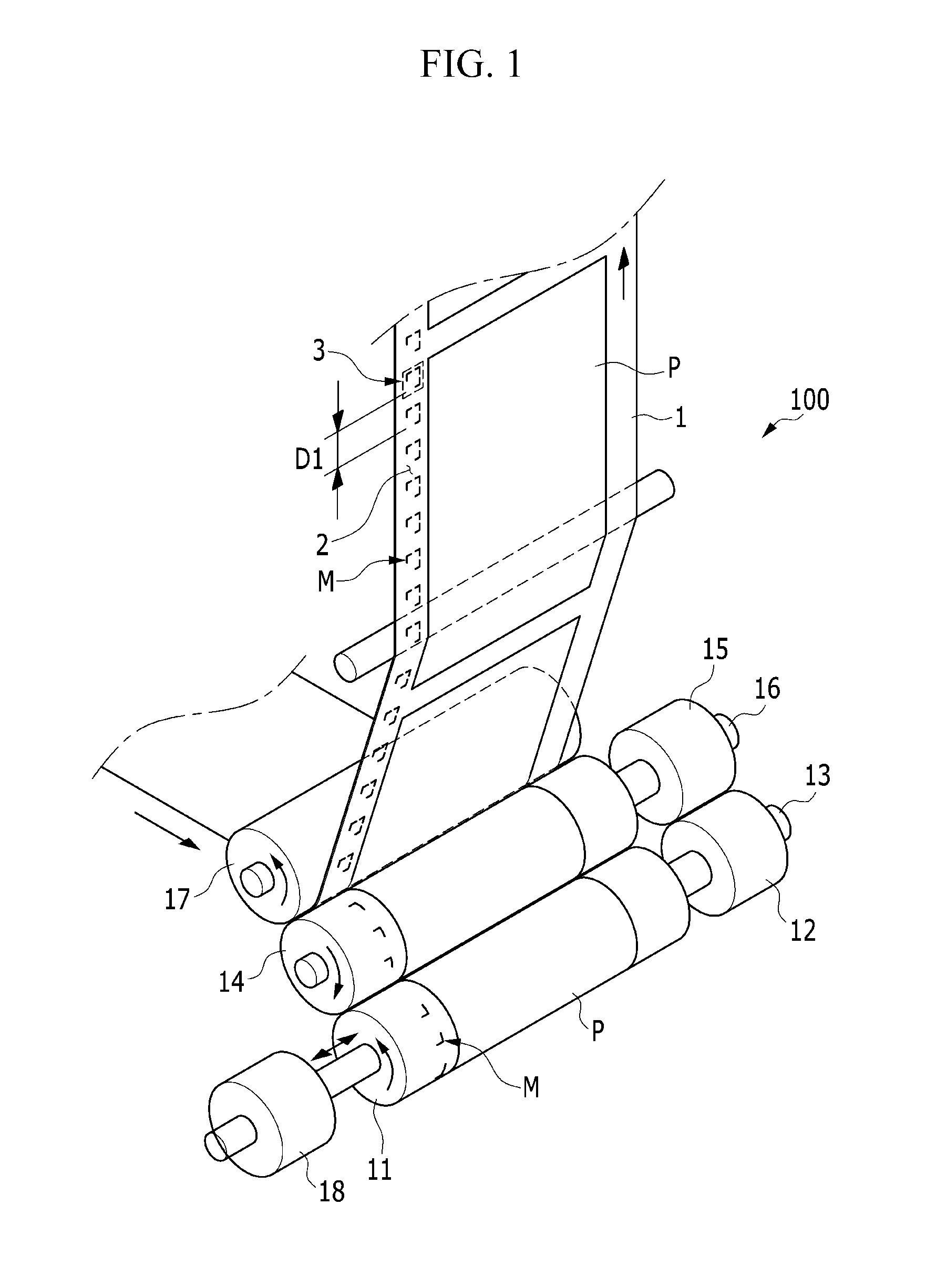
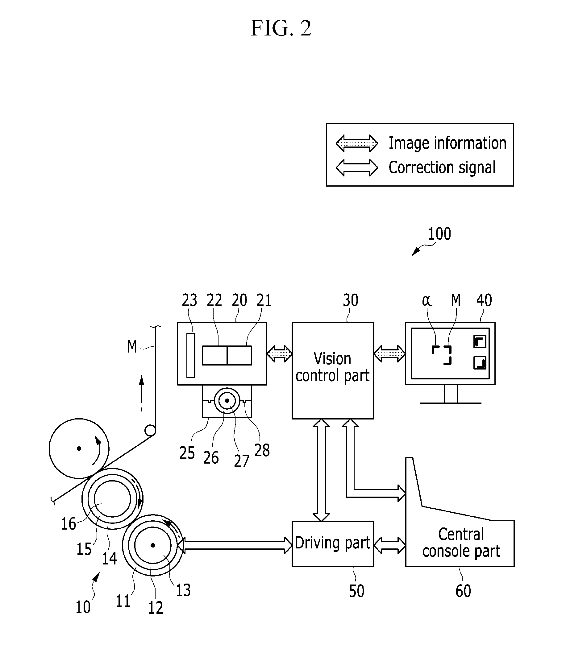

Image

  • Precision overprinting method of printed electronics rotary printing where location can be adjusted in real time
  • Precision overprinting method of printed electronics rotary printing where location can be adjusted in real time
  • Precision overprinting method of printed electronics rotary printing where location can be adjusted in real time

Examples


Embodiment Construction

[0027]Before describing various exemplary embodiments of the present invention in detail, it can be seen that applications thereof are not limited to details of configurations and arrangements of constituent elements which are described in the following detailed description or illustrated in the drawings. The present invention may be realized and carried out by other embodiments, and may be performed in various methods. Further, it can be seen that expressions and wordings used herein regarding such terms as directions (for example, “front”, “back”, “up”, “down”, “top”, “bottom”, “left”, “right”, and “lateral”) of devices or elements are used only to simplify the description of the present invention and do not represent or mean that the related devices or element needs to have specific directions simply. In addition, terms such as “first” and “second” are used in the specification and the accompanying drawings for description, and are not intended to represent or mean relative impor...


PUM


Abstract

The present invention relates to a precision overprinting method of printed electronics rotary printing where a location can be adjusted in real time. More particularly, minute precise printing electronic patterns of a micrometer level which are multilayered by a plurality of gravure offset printing units are accurately overprinted, and a fine deviation in a rotation direction and an axial direction of a plate cylinder is quickly solved. The present invention also relates to a precision overprinting method of printed electronics rotary printing where a location can be adjusted in real time, capable of verifying a printing quality by displaying register marks printed in printing units and alignment state on a display device.

Description

BACKGROUND OF THE INVENTION[0001](a) Field of the Invention[0002]The present invention relates to a technology of accurately aligning various functional circuit layers with printing units to perform precision overprinting when simple electronic elements such as resistors and electrode circuits are precisely overprinted in the same pattern to be printed or a micrometer size electronic printing product where electronic circuits such as accumulators, diodes, transistors, and integrated circuits are multilayered is overprinted by a gravure offset rotary printer including a plurality of gravure offset rotary printing units.[0003](b) Description of the Related Art[0004]The technology associated with the present invention is based on ‘a method and an apparatus for manufacturing an electronic element using a roll-to-roll rotary printing method’ filed by the applicant (Korean Application No. 10-2005-30722) and registered on Oct. 9, 2006 (Korean Patent No. 10-0634327).[0005]In the registered ...

Claims


Application Information

Patent Timeline
Patent Type & Authority Applications(United States)
IPC IPC(8): B41F1/34
CPCB41F13/14B41F9/01B41F33/0081
Inventor CHOI, BYUNG-OHRYOO, BYUNG-SOONLIM, KYU JINKIM, DONG-SOOJO, JEONG DAI
Owner KOREA INST OF MACHINERY & MATERIALS
Learn More