Damping Apparatus for Flywheel

Inactive Publication Date: 2014-03-27
HYUNDAI MOTOR CO LTD
View PDF3 Cites 5 Cited by
  • Summary
  • Abstract
  • Description
  • Claims
  • Application Information

AI Technical Summary

Benefits of technology

The present invention provides a damping apparatus of a flywheel that keeps the rotational balance and the center of gravity of a weight, and reduces the number of holes formed in the rotors to increase the inertia of the rotors and enhance the durability of the rotors. The weight can be interposed between the rotors, making it easy to control the center of gravity and inertia and improve the performance of the damping apparatus. Moreover, the installation of a pin that fastens the rotors does not interfere with the weight, improving the durability of the rotors and solving the problem of reduced weight of the rotors due to hole formation.

Problems solved by technology

Generally, in internal combustion engines, variation in piston gas pressure inevitably causes an imbalance of drive force.
However, in the case of such engines, as shown in FIG. 1, a torsional exciting force of the engine is further increased, thus worsening NVH problems such as rattle and booming.
Further, shock and noise attributable to rattle resulting from an increase in the magnitude of torsional vibration are further increased in shift gear pairs of a transmission.
However, in the conventional damping apparatus, the weights are provided on opposite sides of the rotational flange so that it is very difficult to correctly adjust the rotational balance and the center of gravity of the weights that are disposed at opposite positions.
The formation of the holes causes problems of not only the weight of the rotational flange being reduced but also the durability of the rotational flange being weakened.
Further, the formation of the holes makes it more difficult to adjust the rotational balance of the weights.

Method used


Image

  • Damping Apparatus for Flywheel
  • Damping Apparatus for Flywheel
  • Damping Apparatus for Flywheel

Examples


Embodiment Construction

[0033]Reference will now be made in detail to various embodiments of the present invention(s), examples of which are illustrated in the accompanying drawings and described below. While the invention(s) will be described in conjunction with exemplary embodiments, it will be understood that present description is not intended to limit the invention(s) to those exemplary embodiments. On the contrary, the invention(s) is / are intended to cover not only the exemplary embodiments, but also various alternatives, modifications, equivalents and other embodiments, which may be included within the spirit and scope of the invention as defined by the appended claims.

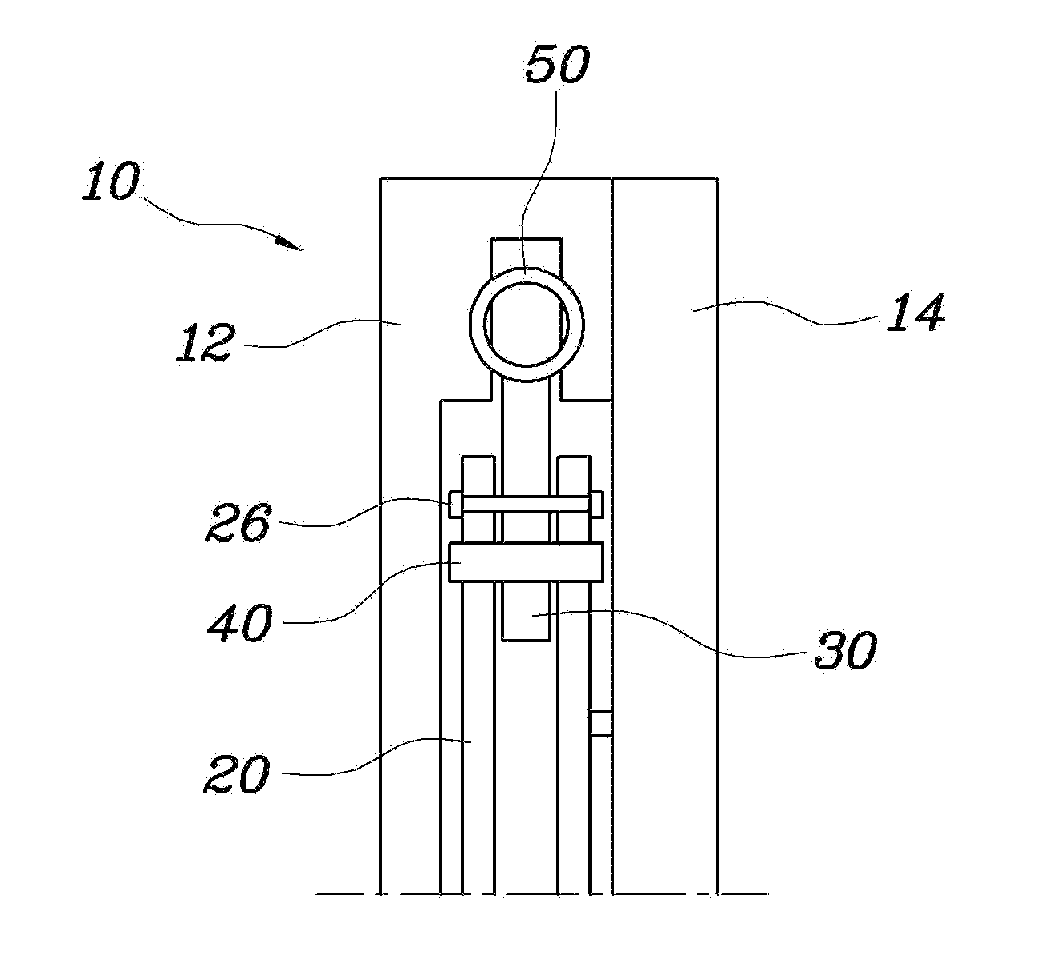
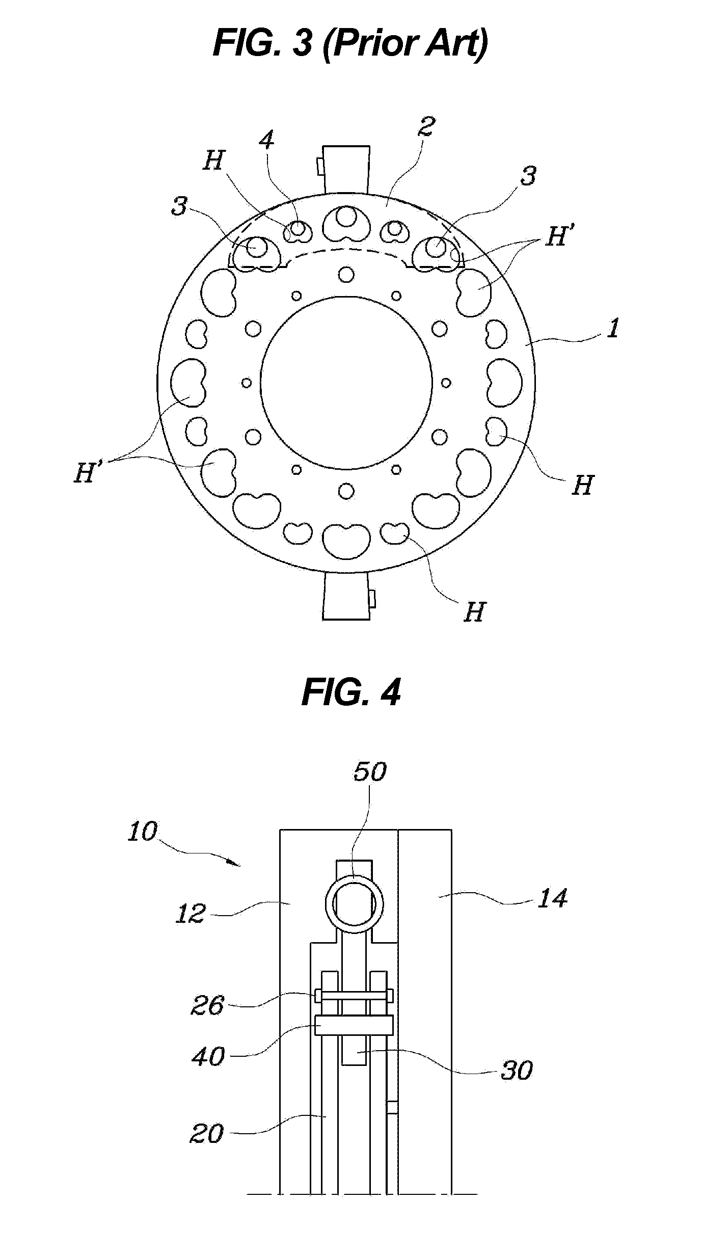
[0034]As shown in FIGS. 4 through 9, a damping apparatus for flywheels according to the present invention includes a pair of rotors 20 and weights 30. The rotors 20 are provided in a flywheel 10 and rotate along with it. The rotors 20 receive torsional vibration from an engine through the flywheel 10. The rotors 20 face each other and...


PUM


Abstract

A damping apparatus of a flywheel includes a pair of rotors and a weight. The rotors are provided in the flywheel and rotate along with the flywheel. The rotors receive torsional vibration from an engine through the flywheel, and are configured such that they face each other and are restricted from rotating relative to each other. The weight is provided between the rotors. The weight rotates relative to the rotors in a direction in which the torsional vibration transmitted to the rotors is offset.

Description

CROSS-REFERENCE TO RELATED APPLICATION[0001]The present application claims priority of Korean Patent Application Number 10-2012-0105472 filed Sep. 21, 2012, the entire contents of which application is incorporated herein for all purposes by this reference.BACKGROUND OF INVENTION[0002]1. Field of Invention[0003]The present invention relates generally to damping apparatuses for flywheels and, more particularly, to a damping apparatus for a flywheel in which a weight is installed between two rotors, thus having an advantage of maintaining the rotational balance and the center of gravity of the weight, and which is configured such that the number of holes formed in the rotors is reduced, thus increasing the inertia of the rotors, and enhancing the durability of the rotors.[0004]2. Description of Related Art[0005]Generally, in internal combustion engines, variation in piston gas pressure inevitably causes an imbalance of drive force. As a result, a torsional exciting force is generated i...

Claims


Application Information

Patent Timeline
IPC IPC(8): F16F15/30
CPCF16F15/30F16F15/145Y10T74/2128F16F15/31
Inventor OH, WAN SOO
Owner HYUNDAI MOTOR CO LTD
Why Eureka
Try Eureka