
Mobile communication method, mobile station, core network device, and radio base station

Inactive Publication Date: 2014-03-20
NTT DOCOMO INC
View PDF2 Cites 17 Cited by
  • Summary
  • Abstract
  • Description
  • Claims
  • Application Information

AI Technical Summary

Benefits of technology

The present invention provides a mobile communication method, a mobile station, a core network device, and a radio base station capable of switching a communication state in which transmission / reception of a data signal is performed between mobile stations without through a radio link in a radio base station interface set between a mobile station and a radio base station, and providing remedies when the quality of the radio link in the Ud interface is deteriorated. This helps to reduce the processing load on the radio base station and provides better service to users.

Problems solved by technology

However, in a conventional LTE mobile communication system, it is configured such that both of a data signal and a control signal are transmitted / received through the radio base station eNB even if a plurality of mobile stations UE is arranged in the same cell (or in a cell under control of the radio base station eNB), and thus there is a problem that a processing load of the radio base station eNB may be increased.
However, in the mechanism of the conventional LTE mobile communication system, when the plurality of mobile stations UE transmits / receives a data signal through the radio link in the Ud interface, there is a problem that there are no remedies when the quality of the radio link in the Ud interface is deteriorated.

Method used


Image

  • Mobile communication method, mobile station, core network device, and radio base station
  • Mobile communication method, mobile station, core network device, and radio base station
  • Mobile communication method, mobile station, core network device, and radio base station

Examples


first embodiment

A Mobile Communication System According to the Present Invention

[0026]A mobile communication system according to a first embodiment of the present invention will be described with reference to FIGS. 1 and 5.

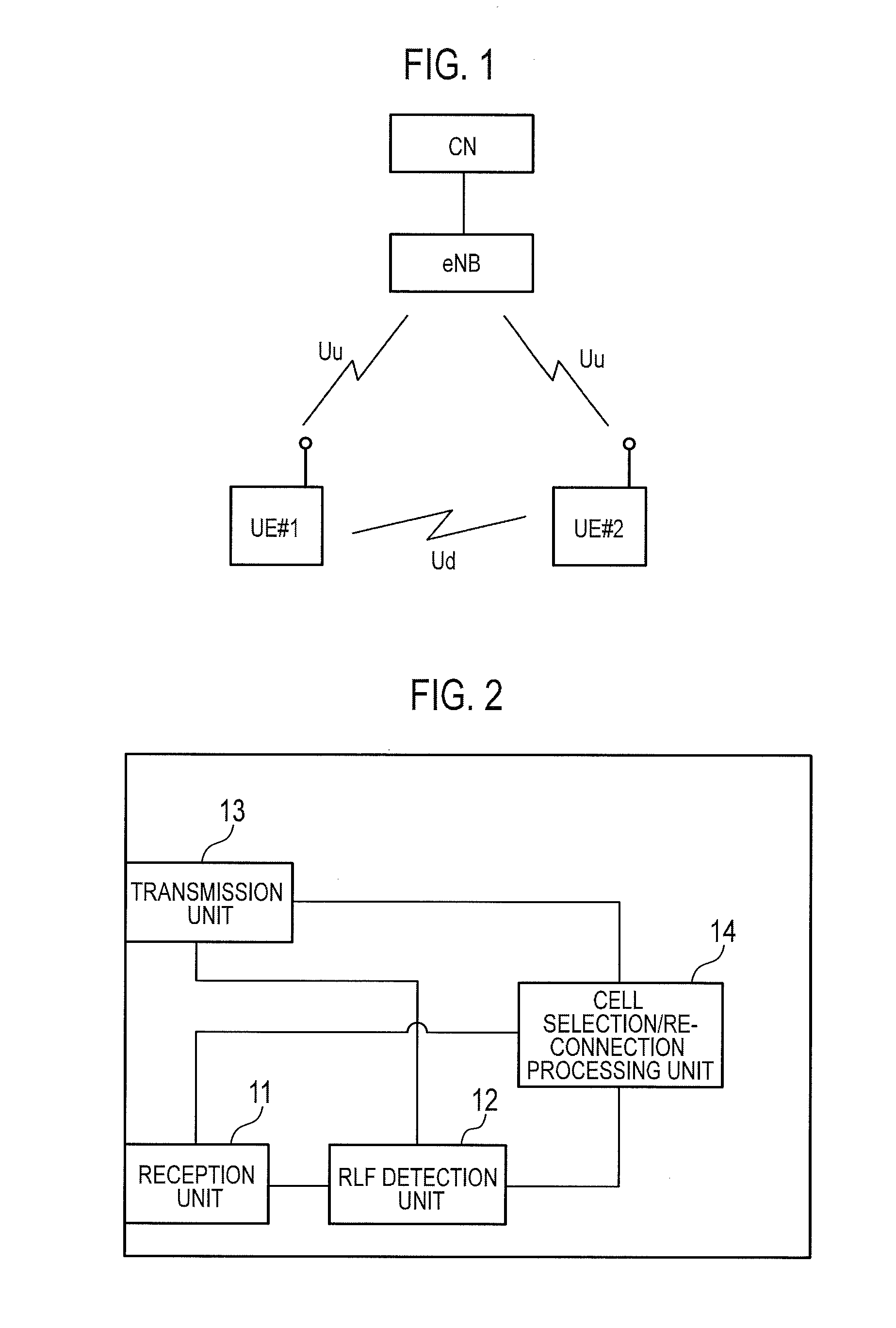
[0027]A mobile communication system according to the present embodiment is an LTE mobile communication system, and is, as illustrated in FIG. 1, includes a core network device CN and a radio base station eNB connected under control of the core network device CN. Note that the present invention is applicable to a cellular mobile communication system other than the LTE system.

[0028]Here, it is configured such that, in a first communication state, a data signal is transmitted / received between a mobile station UE#1 and a mobile station UE#2 through a radio link in a Ud interface set between the mobile station UE#1 and the mobile station UE#2 without through a radio link in Uu interfaces set between the radio base station eNB and the mobile stations.

[0029]Note that, as for a control s...

modification example 1

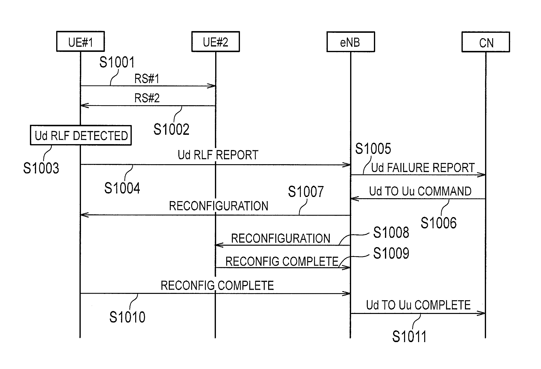
[0068]In a mobile communication system according to a modification example 1, a radio base station eNB may be configured to transmit, to a mobile station UE#1 and a mobile station UE#2, “Reconfiguration” that instructs transition from a first communication state to a second communication state without transmitting “Ud Failure Report” to a core network device CN when the radio base station eNB receives “Ud RLF Report” from the mobile station UE#1 and the mobile station UE#2.

[0069]The above-described characteristics of the present embodiment may be expressed as follows.

[0070]A first characteristic of the present embodiment is a mobile communication method capable of switching a first communication state in which transmission / reception of a data signal is performed between a mobile station UE#1 (first mobile station) and a mobile station UE#2 (second mobile station) through a radio link in a Ud interface (interface between mobile stations) set between the mobile station UE#1 and the mo...


PUM


Abstract

To provide remedies when the quality of a radio link in a Ud interface is deteriorated. In a mobile communication method according to the present invention, a first communication state in which transmission / reception of a data signal is performed between a mobile station UE#1 and a mobile station UE#2 through a radio link in a Ud interface set between the mobile station UE#1 and the mobile station UE#2 without through a radio link in a Uu interface set between a mobile station and a radio base station eNB, and a second communication state in which transmission / reception of a data signal is performed between the mobile station UE#1 and the mobile station UE#2 through the radio link in the Uu interface can be switched. When the mobile station UE#1 detects RLF in the Ud interface in the first communication state, the mobile station UE#1 transits to the second communication state.

Description

TECHNICAL FIELD[0001]The present invention relates to a mobile communication method, a mobile station, a core network device, and a radio base station.BACKGROUND ART[0002]In a long term evolution (LTE) system, a mobile station UE is configured to receive a signal such as a reference signal (RS) from a radio base station eNB in a radio link in a Uu interface, and to monitor the quality of the signal (signal to interference ratio, SIR).[0003]To be specific, the mobile station UE is configured to detect radio link failure (RLF) as described below using parameters N310, N311, and T310 set with a radio resource control (RRC) message by the radio base station eNB.[0004]In the mobile station UE, a physical layer measures the quality (SIR) of a received signal (RS), and notifies an RRC layer of “out-of-sync” when the quality is “Qout” or less, and notifies the RRC layer of “in-of-sync” when the quality is “Qin” or more.[0005]Here, when the quality falls between “Qin” and “Qout”, the physica...

Claims


Application Information

Patent Timeline
IPC IPC(8): H04W72/04
CPCH04W72/0413H04W88/06H04W92/18H04W76/23H04W76/19H04W76/14H04W72/21
Inventor IWAMURA, MIKIOTAKAHASHI, HIDEAKI
Owner NTT DOCOMO INC
Learn More