
Linear generator and method for generating power using the same

Inactive Publication Date: 2014-03-06
IND ACADEMIC CORP FOUND YONSEI UNIV
View PDF0 Cites 16 Cited by
  • Summary
  • Abstract
  • Description
  • Claims
  • Application Information

AI Technical Summary

Benefits of technology

The present invention provides a linear generator with a unique structure that reduces cogging force, and a method for generating power using it. Additionally, it offers a flux concentration method for configuring a rotor without using adhesive, which increases space efficiency of magnets and a method for generating power using it.

Problems solved by technology

To this end, a flywheel, fluid pump, or the like may be used, but in this case, there are disadvantages such as mechanical energy loss and a weak point occurring in the mechanical structure.
The linear generator is less competitive than the rotary generator due to disadvantages such as high manufacturing costs and low efficiency for the price as compared to the rotary generator.
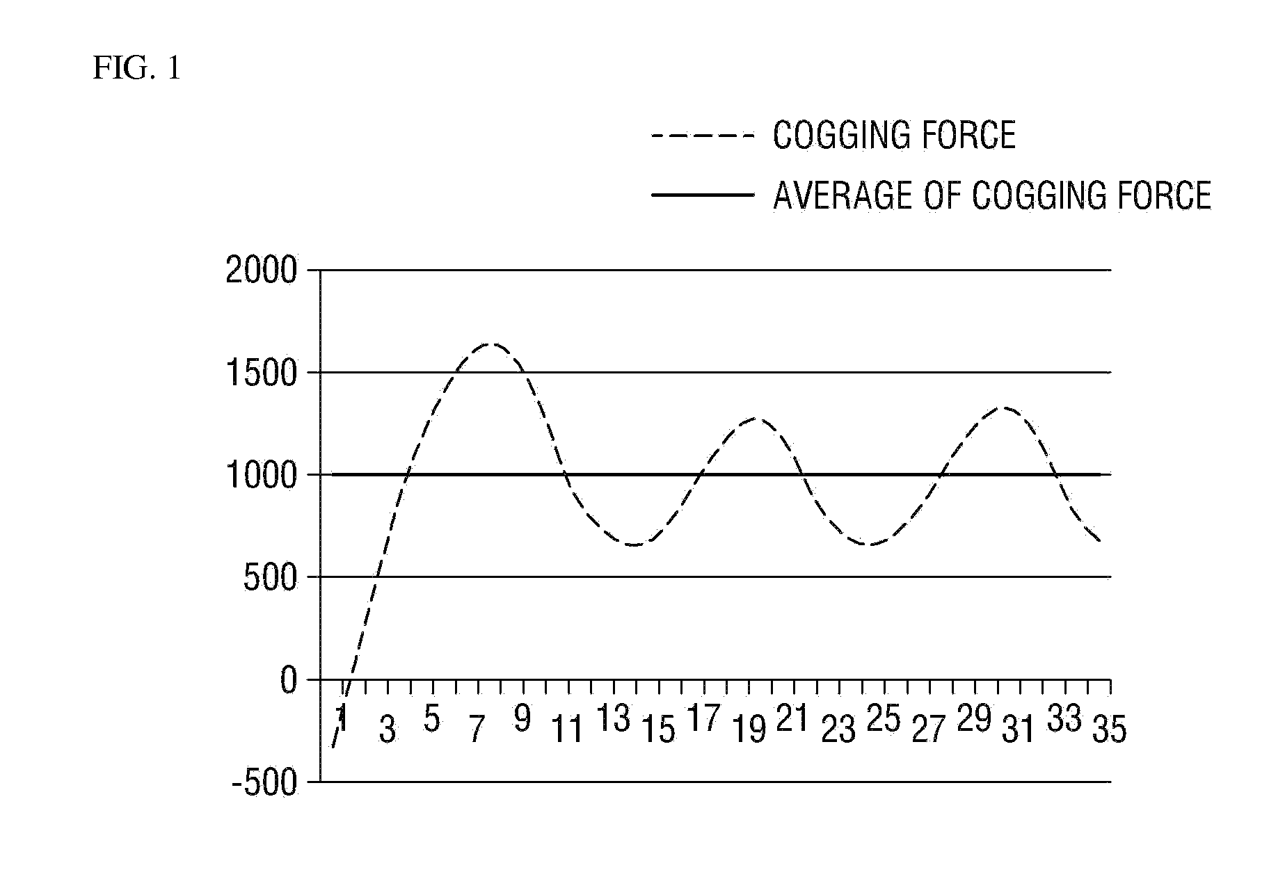
In the linear generator, since the speed of the rotor is extremely slow compared to a rotary generator, it is necessary to attenuate a cogging force.
However, there still occurs a problem that there is a phase difference of 36 degrees between adjacent slots.
However, it is possible to produce a three-phase AC power by properly arranging the order in which the coils are connected, but it is impossible to completely reduce the cogging force even if the phase difference is used.
However, since the cogging force itself does not form perfect bilateral symmetry, perfect offset is difficult.
There is inconvenience in the assembly that a separate adhesive should be used in order to attach the magnets.

Method used


Image

  • Linear generator and method for generating power using the same
  • Linear generator and method for generating power using the same
  • Linear generator and method for generating power using the same

Examples


Embodiment Construction

[0045]The present invention will now be described more fully hereinafter with reference to the accompanying drawings, in which preferred embodiments of the invention are shown. This invention may, however, be embodied in different forms and should not be construed as limited to the embodiments set forth herein. Rather, these embodiments are provided so that this disclosure will be thorough and complete, and will filly convey the scope of the invention to those skilled in the art. The same reference numbers indicate the same components throughout the specification. In the attached figures, the thickness of layers and regions is exaggerated for clarity.

[0046]Unless defined otherwise, all technical and scientific terms used herein have the same meaning as commonly understood by one of ordinary skill in the art to which this invention belongs. It is noted that the use of any and all examples, or exemplary terms provided herein is intended merely to better illuminate the invention and is...


PUM


Abstract

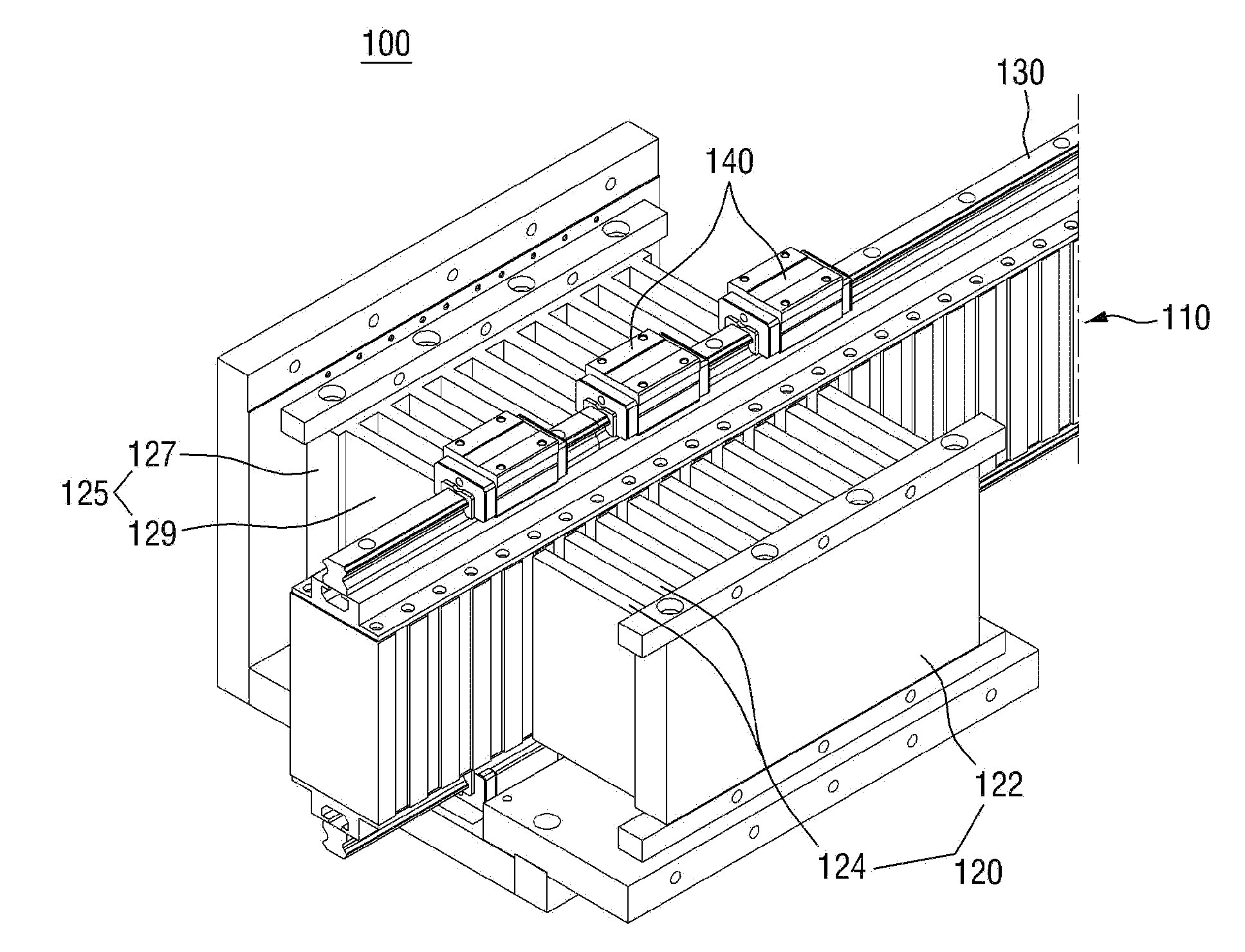
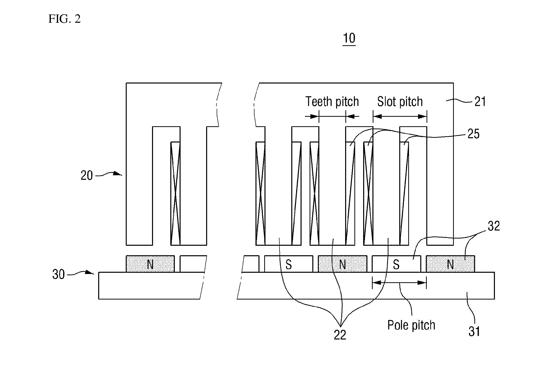
A linear generator and a method for generating power using the same are provided. The linear generator includes a magnet module including magnets located between a plurality of flux concentration blocks, the magnets located on both sides of each of the flux concentration blocks being arranged such that the magnets having the same pole face each other, and a magnetic flux generated from the magnets is induced into both ends of each of the flux concentration blocks; and core modules including coils and located on both sides of the magnet module to generate induced electromotive forces in the coils by the magnetic flux as the core modules move

Description

CROSS-REFERENCE TO RELATED APPLICATION[0001]This application claims priority from Korean Patent Application No. 10-2012-0097243 filed on Sep. 3, 2012 in the Korean Intellectual Property Office, and all the benefits accruing therefrom under 35 U.S.C. 119, the contents of which in its entirety are herein incorporated by reference.BACKGROUND[0002]1. Technical Field[0003]The present inventive concept relates to a linear generator and a method for generating power using the same, and more particularly to a linear generator using a flux concentration method capable of efficiently configuring a space of magnets, and a method for generating power using the same.[0004]2. Description of the Related Art[0005]Wave energy is one type of ocean energy, which means vibration energy of seawater by wind. The waves have energy of reciprocating motion of seawater moving vertically or horizontally unlike the tide. An apparatus that converts the kinetic energy into useable energy is generally a wave ener...

Claims


Application Information

Patent Timeline
IPC IPC(8): H02K1/17H02K35/00
CPCH02K35/00H02K1/17H02K29/03H02K35/04H02K41/031H02K2213/03H02K41/02H02K41/03
Inventor PARK, JIN BAEKIM, JAE MANSONG, MIN KOOKSONG, SEUNG KWANKIM, JUNG YOONKIM, JAE SEUNG
Owner IND ACADEMIC CORP FOUND YONSEI UNIV
Learn More