
Liquid Natural Gas Storage Tank Mounting System

a technology for liquid natural gas storage tanks and mounting systems, which is applied in the direction of transportation and packaging, transportation items, manufacturing tools, etc., can solve the problems of inability to maintain the inner tank at the low temperature, the inability of lng powered machines to be used to power movable machines, and the inability to provide lng powered machines without difficulties

Active Publication Date: 2014-03-06
CATERPILLAR INC
View PDF20 Cites 19 Cited by
  • Summary
  • Abstract
  • Description
  • Claims
  • Application Information

AI Technical Summary

Benefits of technology

This patent is about a system for mounting a fuel tank on a movable machine. It includes a tank, a spring that connects the tank to the machine's frame, and a shock absorber that connects the tank to the frame. This system helps reduce the chances of damage to the fuel tank during transportation or operation of the machine. Additionally, this patent also describes a method for mounting the tank on the machine. Overall, this patent provides a solution for safely and securely mounting fuel tanks on movable machines.

Problems solved by technology

LNG machines can not only be used to power movable machines such as automobiles for over the highway use, but also to power many work machines used in industrial, construction, and agricultural settings such as, but not limited to, dump trucks, loaders, excavators, and the like.
While effective, LNG powered machines are currently not provided without difficulties.
As a result of the transmitted vibration and shock loads and inner structure damage that may result from such loading, the inner tank may not be able to be maintained at the low temperature desired, or if it is able to maintain such a temperature, can do so only at a lesser efficiency than prior to the damage.
Such damage is particularly likely with movable machines subjected to very large vertical loads.
With conventional LNG storage tank mounting systems, no dedicated structure of system is specifically provided to enable the tank to handle such vertical loads and thus the 130 ton load exerted against the trucks accelerates the truck rapidly enough to induce large loads against the ING storage tank.

Method used


Image

  • Liquid Natural Gas Storage Tank Mounting System
  • Liquid Natural Gas Storage Tank Mounting System
  • Liquid Natural Gas Storage Tank Mounting System

Examples


Embodiment Construction

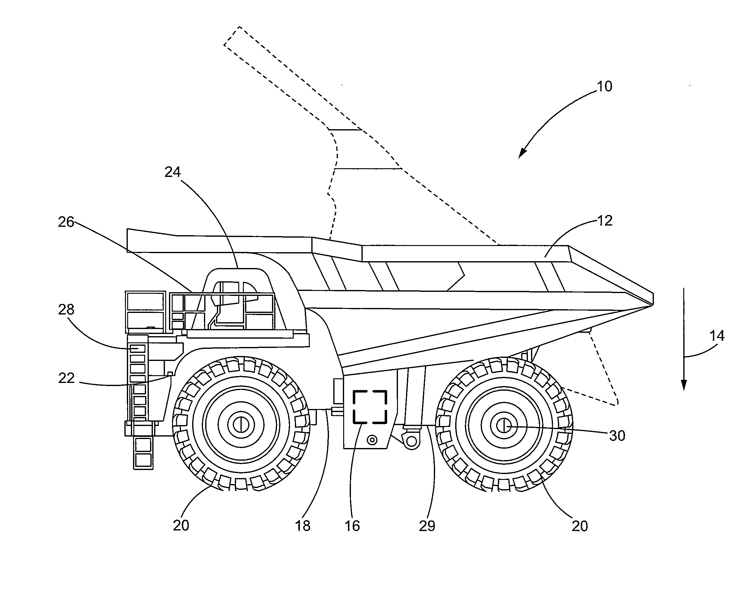
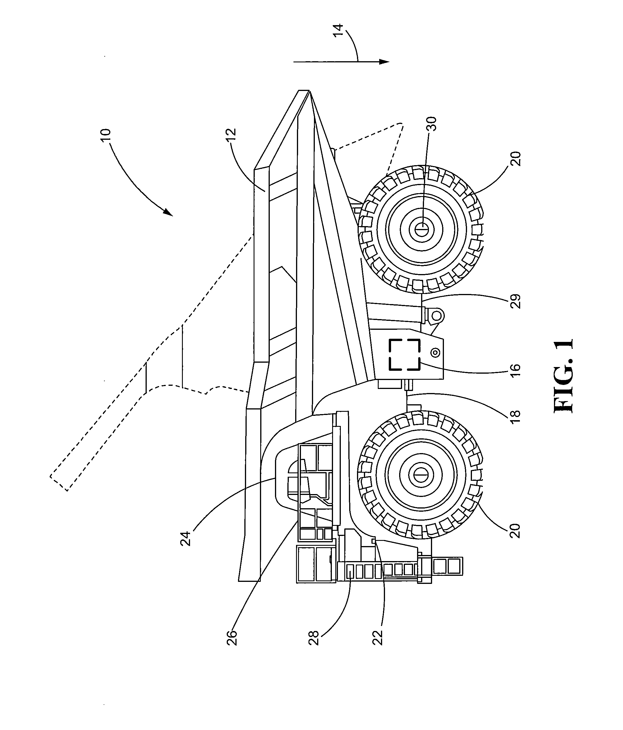
[0018]Referring now to the drawings, with specific reference to FIG. 1, a movable machine constructed in accordance with the teachings of this disclosure is generally referred to by reference numeral 10. As shown therein, machine 10 may be provided in the form of a dump truck in this case a large mining truck (LMT), but the teachings of this disclosure can find applicability in connection with any number of different movable machines including, but not limited to, smaller trucks, articulated trucks, loaders, excavators, pipe layers, motor graders, and the like. However, the machine 10 depicted in FIG. 1 is an LMT as the teachings of this disclosure can find particular applicability in connection with machines 10 which are subjected to significant vertical loads. An LMT is one such machine in that it is subjected to significant vertical loads due to the fact that the overall payload of such a machine may be on the order of or excess of 400 tons. Moreover, as such machines are loaded ...


PUM


Abstract

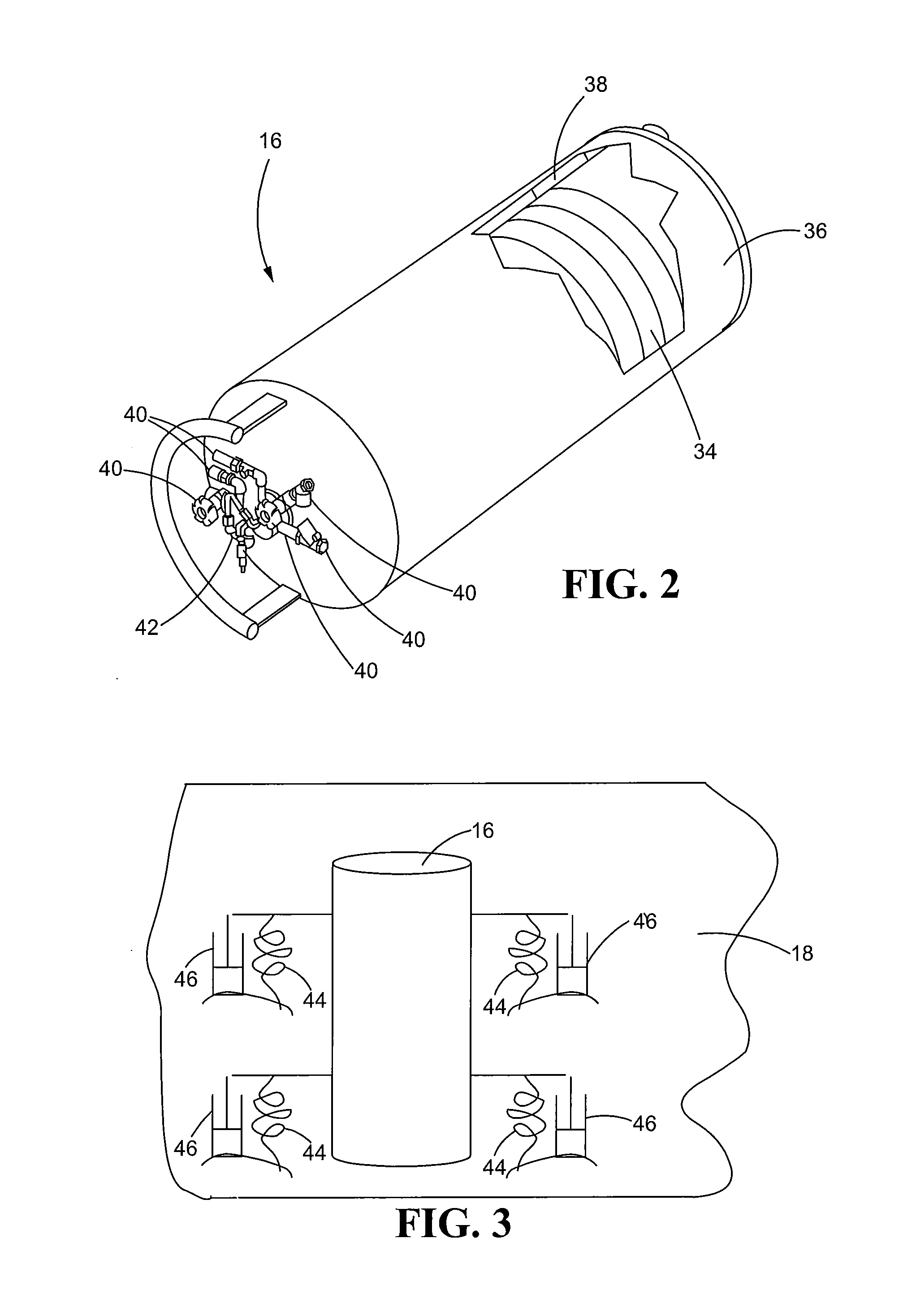
A fuel tank mounting system for movable machine is disclosed. The mounting system may include a fuel tank connected to a frame of the movable machine in such a manner as to allow vertical motion of the tank relative to the frame. The fuel tank may be mounted to the frame using a spring and / or a shock absorber. The fuel tank may be a cryogenic fuel tank for storage of liquid natural gas. The shock absorbers may be tunable so that the level of dampening provided by the shock absorber is tailored to the type of machine and the specific mode of operation of the machine.

Description

FIELD OF THE DISCLOSURE[0001]The present disclosure generally relates to fuel tanks and, more particularly, relates to fuel tanks mounted on moving machines.BACKGROUND OF THE DISCLOSURE[0002]The use of liquid natural gas (LNG) for powering movable machines is becoming increasingly popular. Among other things, LNG engines have a reduced carbon output and thus are viewed as more environmentally friendly than conventional diesel and other internal combustion engines powered by gasoline. In addition, given the prevalence of LNG (primarily methane), the cost associated with such fuel is lower than other fuel products and thus consumer demand for such machines is increasing. LNG machines can not only be used to power movable machines such as automobiles for over the highway use, but also to power many work machines used in industrial, construction, and agricultural settings such as, but not limited to, dump trucks, loaders, excavators, and the like.[0003]While effective, LNG powered machi...

Claims


Application Information

Patent Timeline
IPC IPC(8): B60K15/07B23P11/00B62D65/02B62D33/00
CPCB60K15/07B60K15/063B60Y2200/142Y10T29/49826
Inventor WILLI, MARTIN LEO
Owner CATERPILLAR INC
Learn More