
Ultrasound diagnostic imaging apparatus and ultrasound diagnostic imaging method

a diagnostic imaging and ultrasonic technology, applied in ultrasonic/sonic/infrasonic image/data processing, instruments, applications, etc., can solve the problems of insufficient reflection intensity and inconvenient spatial compounding method for visualizing anisotropics

Active Publication Date: 2014-02-13
KONICA MINOLTA INC
View PDF1 Cites 21 Cited by
  • Summary
  • Abstract
  • Description
  • Claims
  • Application Information

AI Technical Summary

Benefits of technology

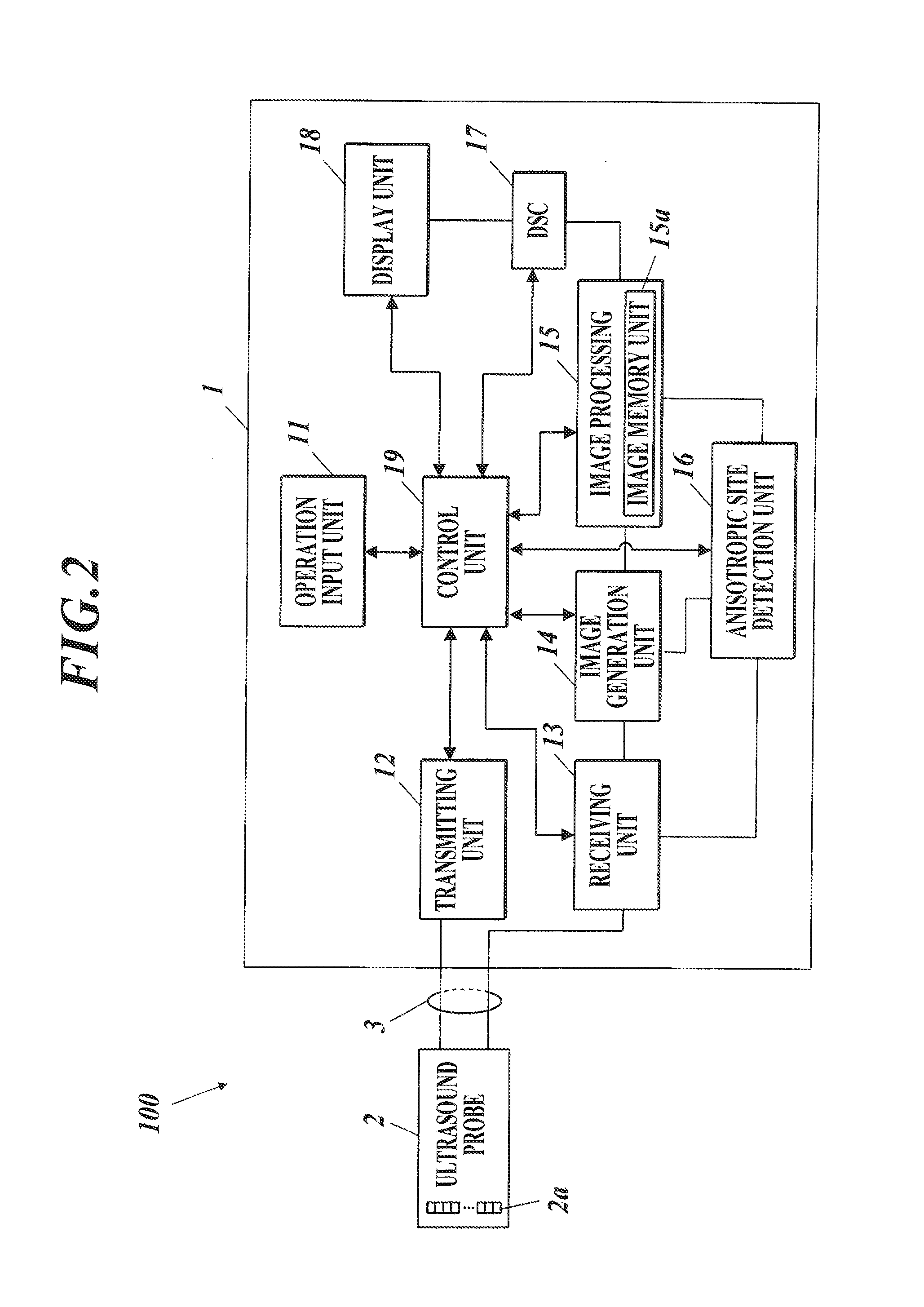
The present invention provides an ultrasound diagnostic imaging apparatus and method that can clearly visualize anisotropic sites in soft tissues, such as tendons and ligaments, which show great reflection intensity but are not easily visualized using conventional methods. The apparatus includes an ultrasound probe that obtains receive signals by driving a plurality of transducers and performing ultrasound scanning. The received signals are converted into luminescence data sets and an anisotropic aspect evaluation unit evaluates the anisotropic aspect of the reflected ultrasound waves. The image processing unit synthesizes multiple ultrasound image data sets according to the evaluation results and the depth rate of the receive focal point with respect to the transducers. The apparatus can set different transmission / reception conditions based on the evaluation results to optimize imaging. Overall, the invention improves the accuracy of ultrasound imaging for soft tissues and allows for better detection and treatment of injuries.

Problems solved by technology

However, the conventional spatial compounding method is not satisfactory for visualizing anisotropic sites in soft tissues showing specular reflection characteristics but the reflection intensity not being as intensive as bone surfaces due to their fibrous structure, such as tendons and ligaments in skeletal muscles.

Method used


Image

  • Ultrasound diagnostic imaging apparatus and ultrasound diagnostic imaging method
  • Ultrasound diagnostic imaging apparatus and ultrasound diagnostic imaging method
  • Ultrasound diagnostic imaging apparatus and ultrasound diagnostic imaging method

Examples


embodiment example 1

[0229]In embodiment example 1, synthetic image data is generated by performing the spatial compounding of the 1st example described above. When performing the spatial compounding, the component image data set corresponding to the scan region having the steering angle of 0° is weighted by 40%, the component image data set corresponding to the scan region having the steering angle of +10° is weighted by 20% and the component image data set corresponding to the scan region having the steering angle of −10° is weighted by 40% (this also applies to embodiment examples 2 to 9, 11 and 12).

embodiment example 2

[0230]In embodiment example 2, synthetic image data is generates by performing the spatial compounding of the 2nd example described above.

embodiment example 3

[0231]In embodiment example 3, synthetic image data is generated by performing the spatial compounding of the 3rd example described above.


PUM


Abstract

Described is an ultrasound diagnostic imaging apparatus which includes an ultrasound probe and which generates ultrasound image data sets for displaying an ultrasound image. The ultrasound diagnostic imaging apparatus includes a transmitting unit which performs ultrasound scanning for a plurality of times so that a part of or all of scan regions overlap in a plurality of different directions, an image processing unit which generates a plurality of ultrasound image data sets according to the receive signals and an anisotropic aspect evaluation unit which evaluates an anisotropic aspect of ultrasound wave reflection in the subject according to at least either of the ultrasound image data sets and the receive signals. In the ultrasound diagnostic imaging apparatus, the image processing unit generates synthetic image data in which the plurality of ultrasound image data sets are synthesized according to an evaluation result of the anisotropic aspect evaluation unit.

Description

BACKGROUND OF THE INVENTION[0001]1. Field of the Invention[0002]The present invention relates to an ultrasound diagnostic imaging apparatus and an ultrasound diagnostic imaging method.[0003]2. Description of Related Art[0004]Conventionally, ultrasound diagnostic imaging apparatuses including ultrasound probes with a plurality of transducers aligned therein are known. Such ultrasound diagnostic imaging apparatuses perform transmission and reception of ultrasound waves with respect to a subject such as a living body, generate ultrasound image data according to signals obtained from the received ultrasound waves and display ultrasound images in the image display apparatuses based on the generated ultrasound image data. Ultrasound diagnosis using such apparatuses can be repeatedly performed because real time subject conditions such as heart beat and fetus movement can be obtained with simple operation by touching the body surface of a subject with an ultrasound probe and such operation ...

Claims


Application Information

Patent Timeline
Patent Type & Authority Applications(United States)
IPC IPC(8): A61B8/08
CPCA61B8/5269A61B8/5253A61B8/4405A61B8/4461A61B8/4494A61B8/461A61B8/463A61B8/467A61B8/5207A61B8/54G01S15/8995
Inventor TANIGUCHI, TETSUYASUZUKI, KENJI
Owner KONICA MINOLTA INC
Learn More