
Cycling safety glasses with rearview mirror

a technology of safety glasses and rearview mirrors, applied in the field of rearview mirrors, can solve the problems of affecting the forward vision of cyclists, affecting the safety of cyclists, and affecting the safety of cyclists, and achieve the effect of convenient removal

Inactive Publication Date: 2014-02-13
STEELE HLDG LLC
View PDF3 Cites 28 Cited by
  • Summary
  • Abstract
  • Description
  • Claims
  • Application Information

AI Technical Summary

Benefits of technology

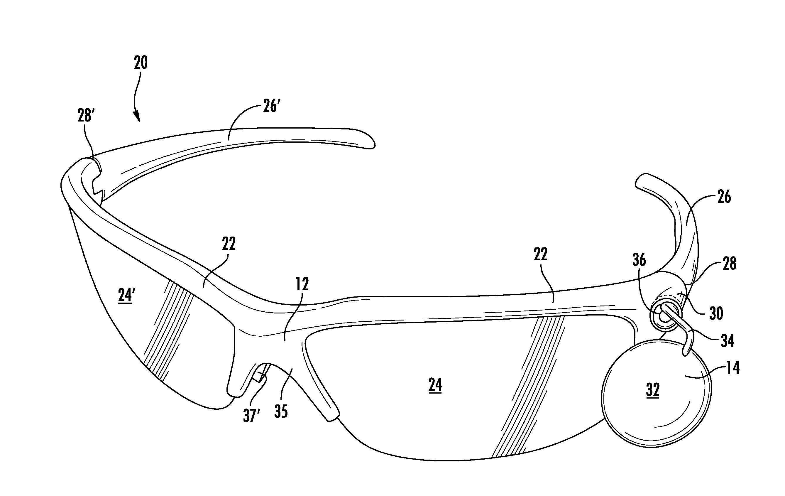
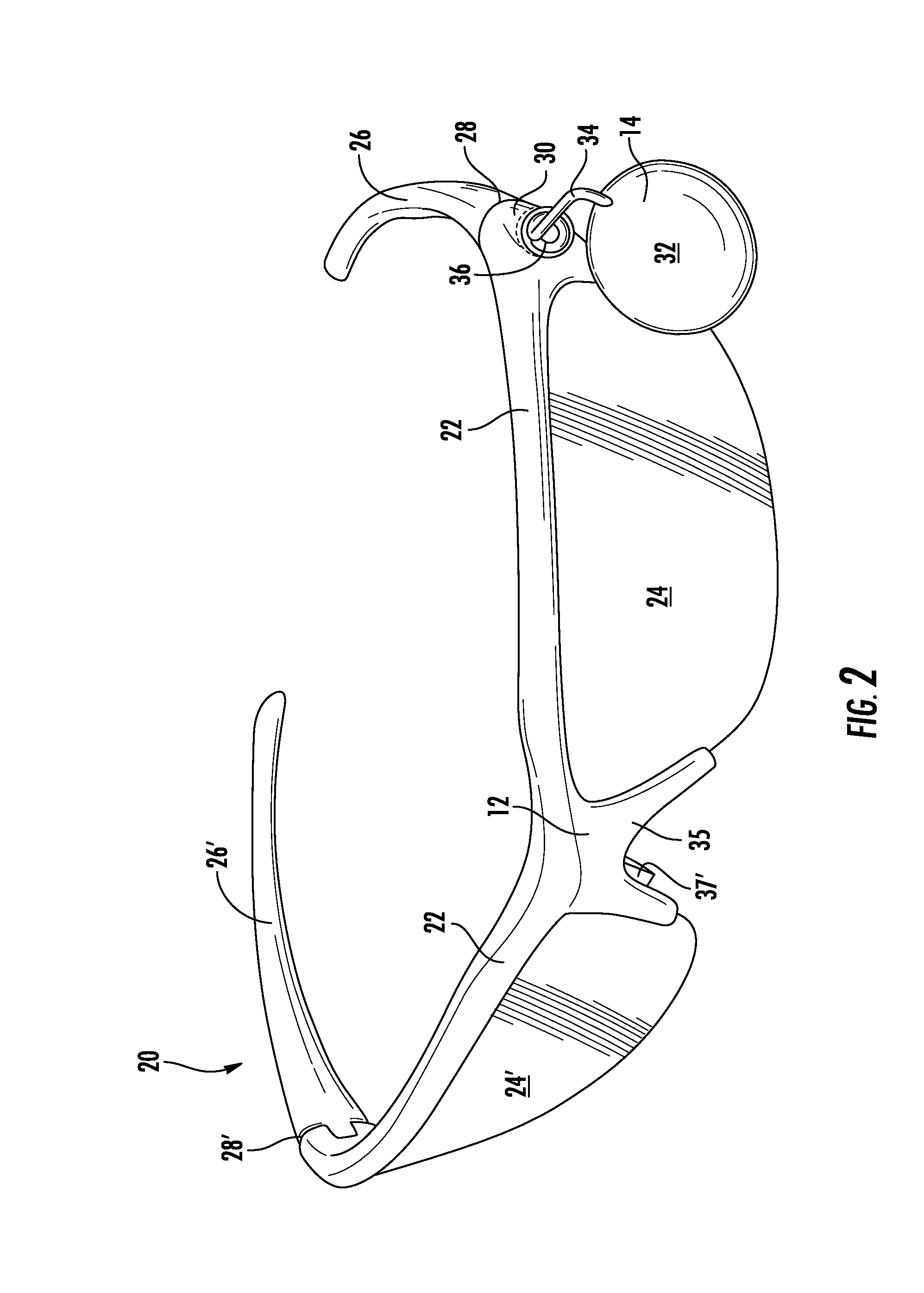
The invention is about a type of eyewear, specifically for cyclists, that has a removable and adjustable rearview mirror. The mirror is attached to the frame of the glasses using a strong magnet, which allows the wearer to adjust the angle of the mirror to see objects behind them. The magnet helps keep the mirror in place while still allowing for easy adjustment by hand. The glasses can also be used without the rearview mirror, or with a different magnet for a different application. The use of a magnet makes the glasses convenient and comfortable for cyclists, and the stem and magnet design ensures that the glasses remain lightweight and easy to wear.

Problems solved by technology

Road cycling in urban environments and on country roads poses unique hazards to the cyclist because of the presence of motorized vehicles, especially cars and trucks.
The growing popularity of group cycling for races, charity rides, and for increased safety in cities and in the country has helped reduce crashes with motorized vehicles, although even an encounter with another approaching bicycle can be quite hazardous, particularly at the speeds achieved by modern experienced cyclists riding in close formation or whenever large groups of riders congregate.
However, these systems typically are somewhat obtrusive and bulky, especially in their attachment to the cyclists' gear, may interfere with the cyclists' forward vision, and have generally not necessarily been widely adopted and used.

Method used


Image

  • Cycling safety glasses with rearview mirror
  • Cycling safety glasses with rearview mirror
  • Cycling safety glasses with rearview mirror

Examples


Embodiment Construction

[0014]This invention can best be understood with reference to the specific embodiments that are illustrated in the accompanying drawings and the variations described below. While the invention will be so described, it should be recognized that the invention is not intended to be limited to the embodiments illustrated in the drawings; rather, the embodiments provided in this disclosure are intended to satisfy applicable legal requirements. The invention includes all alternatives, modifications, and equivalents that may be included within the scope and spirit of the invention as defined by the appended claims.

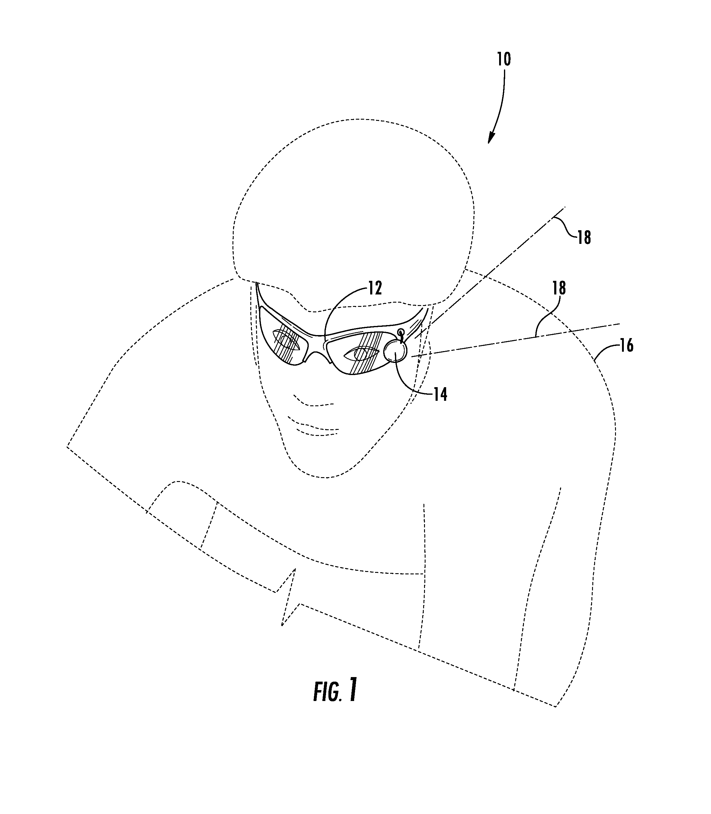
[0015]FIG. 1 illustrates generally at 10 a perspective view of one embodiment of the invention of eyewear 12 having a rearview mirror 14 affixed to the eyewear, the invention shown in solid lines, in the context of the use of the invention by a road cyclist, illustrated in dashed lines at 16. The eyewear in this context is a pair of cycling safety glasses sometimes referred to as...


PUM


Abstract

Safety glasses for experienced cyclists have a small diameter, unobtrusive, adjustable and removable minor mounted thereon for establishing a rearwardly directed line of sight so that the cyclist can see a vehicle, including an automobile, motorcycle, or another cyclist, approaching from behind. The minor is mounted on a stem that is magnetically attached to the gasses frame and extends forward from the frame. The magnetic attachment is sufficient to allow ready adjustment of the angle of incidence of light to establish the desired rearwardly directed line of sight and to fix the line of sight in place after adjustment. The glasses frame has a small disc-shaped neodymium magnet of from about 1 to 2 or 3 pounds force pull strength embedded in the face frame to the wearer's left and the minor stem has a cooperating corresponding magnet mounted opposite the mirror. Larger mirrors may be desirable for use by less experienced cyclists.

Description

FIELD OF THE INVENTION[0001]The invention relates to eyewear having a rearview mirror associated therewith, and, more specifically, to rearview mirrors for mounting on eyewear, to eyewear frames for mounting of a rearview mirror thereon, and to assemblies of eyewear and rearview minors for sports, especially cycling.BACKGROUND OF THE INVENTION[0002]Road cycling in urban environments and on country roads poses unique hazards to the cyclist because of the presence of motorized vehicles, especially cars and trucks. In urban environments, the advent of bicycle lanes has helped alleviate somewhat the danger of being struck from behind by an approaching car or truck, although the prudent cyclist attempts to stay ever alert to automobile traffic. The lanes of county roads frequently have narrow shoulders and cars and trucks may approach less frequently and often at higher speeds demanding of the cyclist a vigilance that can sometimes detract from the enjoyment of the ride. The growing popu...

Claims


Application Information

Patent Timeline
IPC IPC(8): G02C7/14
CPCG02C7/14
Inventor STEELE, CHRISTOPHER M.
Owner STEELE HLDG LLC
Learn More