Air traction belt structure

a technology of air traction and belt structure, which is applied in the field of air traction belt structure, can solve the problems of traction belt useless, traction belts that do not provide the desired support, traction belts that are difficult to use, etc., and achieves the effects of less physical strength and agility, convenient use, and convenient tightening

Active Publication Date: 2014-02-06
HO HOI MING MICHAEL
View PDF5 Cites 2 Cited by
  • Summary
  • Abstract
  • Description
  • Claims
  • Application Information

AI Technical Summary

Benefits of technology

[0009]In view of the aforementioned drawbacks of the conventional air traction belts, the inventor of the present invention conducted extensive research and experiment and finally succeeded in developing an air traction belt structure as disclosed herein. The disclosed air traction belt structure is designed against leakage during inflation and can be easily tightened by a user with relatively less physical strength and agility. Consequently, the air traction belt structure features convenience of use and is enhanced in its supporting, traction, stretching, decompressing and protecting effects.

Problems solved by technology

Most of the traction belts on the market are made of elastic fabrics, including nylon, Lycra fibers, and so on, but these traction belts generally do not provide the desired support, traction, decompression and protection.
If the traction belt is not wrapped around the user's waist very tightly, the upper and lower portion of the traction belt will slip against the user's body and this will render the traction belt useless as it will not provide the traction and decompression effects.
Another problem with the traditional air traction belt is that it is soft and resilient even after it's fully inflated.
Due to it's resiliency, it cannot provide adequate support.
However, the inventor of the present invention has found that most users have problem completing this tightening and fastening action, and those who with relatively less physical agility and strength (e.g., the elderly and the sick) cannot complete this tightening and fastening action at all.
Moreover, in tightening the air traction belt 1, the user's arms are folding inward and crossed awkwardly, which hinders force application.
In addition, the great width of the air fraction belt 1 makes it difficult for the user to grasp the air traction belt 1 and apply pulling forces thereto.
As a result, many users cannot wrap the air traction belt 1 tight enough around the waist in order for the air traction belt 1 to provide sufficient support, traction and protection.
Hence, with frequent leaks, the air pump cannot pump air into the air traction belt 1 efficiently.
Not only does this inefficient pumping process result in a waste of time, but also the user may unknowingly use the air traction belt 1 in a not fully inflated state which provides inadequate support without having traction, stretching or decompression effect to the user's waist.
In addition, in the current market, when a consumer orders a traction belt online or over telephone, he / she often get the traction belt that does not fit him / her properly.
Though the consumer can buy a traction belt from a retail store, he / she may still pick up a fraction belt that does not fit him / her since the salesclerk of the retail store does not know the user's waist size, and the users themselves often doesn't know what their correct waist sizes are.
In fact, a traction belt that is too small cannot be wrapped around the waist, and a traction belt that is too loose will not provide support, traction, stretching and decompression to the consumer's waist, so the right size fitting is essential for the traction belt to provide any benefits to the consumer.
However, the biggest problem of the traditional traction belt is that it is extremely difficult for the manufacture thereof to design a size fitting every consumer's waist size.

Method used


Image

  • Air traction belt structure
  • Air traction belt structure
  • Air traction belt structure

Examples


Embodiment Construction

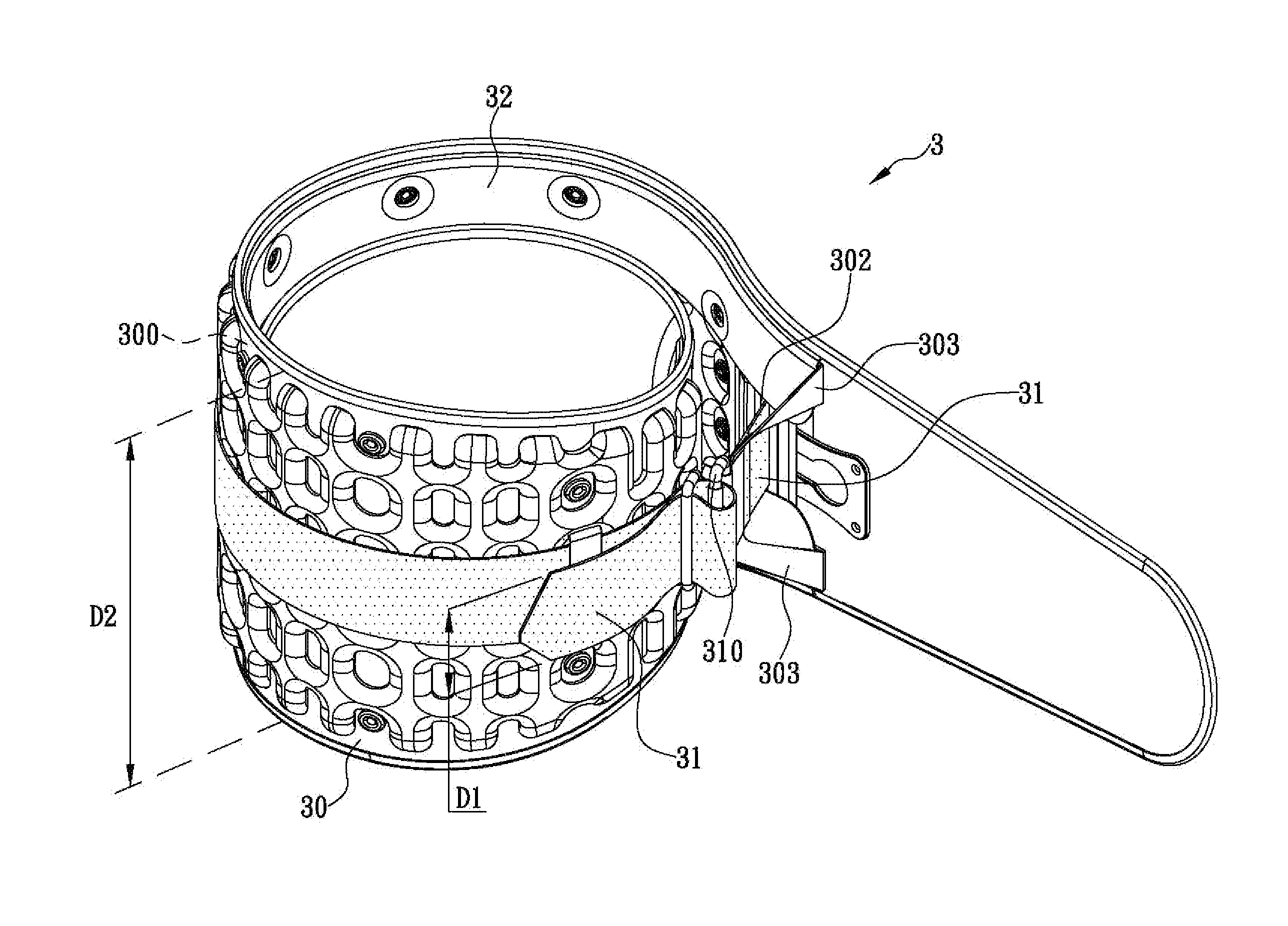
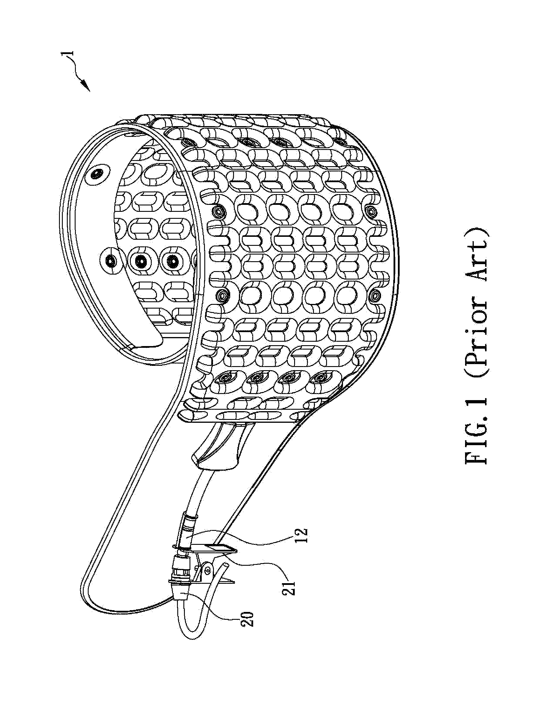
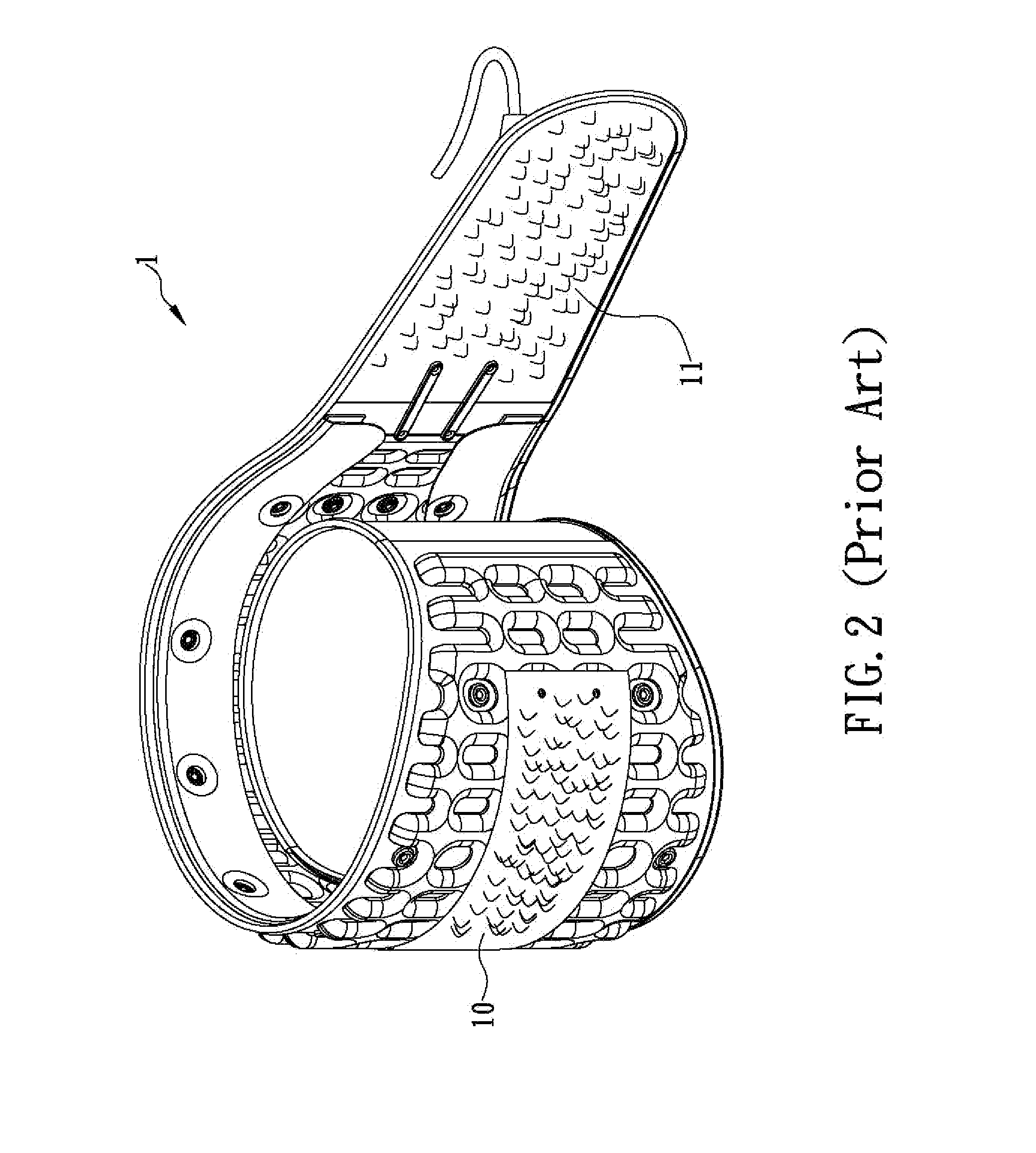
[0026]The inventor of the present invention has long been engaged in research and development in the medical aid-related fields. In the process, the inventor has found that the conventional air fraction belts are very likely to press only loosely against the waist and hence fail to provide the desired support, traction, stretch, decompression and protection. This is not only because the tightening and fastening action required is difficult to perform by those with relatively less physical strength and agility, but also because the conventional air traction belts are too wide to be grasped and pulled. Although attempts have been made to solve the aforesaid problems by further improving the structures of the conventional air traction belts, an ideal solution has yet to be found. In consideration of this, the inventor came up with the idea of movably surrounding an inner inflatable traction belt with an outer solid support belt. Thus, by pulling tight the outer solid support belt, the ...


PUM


Abstract

The present invention is to provide an air traction belt structure, which includes an inner inflatable traction belt having an air valve thereon for communicating with an inflatable space therein and, and an outer solid support belt having a smaller width than the inner inflatable traction belt and movably surrounding outside of the inner inflatable traction belt. Since a first end of the outer solid support belt can pass through a through hole formed on the inner inflatable traction belt and extend to an inner side of the inner inflatable traction belt, a second end of the outer solid support belt can easily pass through a fixing ring provided on the first end of the outer solid support belt and be pulled by a user, for firmly tightening both the inflated inner inflatable traction belt and the outer solid support belt onto the user's waist at the same time.

Description

FIELD OF THE INVENTION[0001]The present invention relates to an air traction belt structure, more particularly to an air traction belt including an outer solid support belt capable of movably surrounding an outer side of an inner inflatable traction belt and easily being pulled by a user, so as for the user to easily and firmly tighten the inflated inner inflatable traction belt onto the user's waist for enhancing the supporting, traction, stretching, decompression and protecting effects to the waist.BACKGROUND OF THE INVENTION[0002]According to a survey conducted in 1994 by the Centers for Disease Control and Prevention (CDC) of the United States regarding how medical aids were used in the US, 47.1% of traction belt users were 44 years old and under, 36.4% were 4˜64 years old, and 16.5% were 65 years old and above. Traction belts—though less frequently used by those 65 years of age and above, who typically make more use of such personal mobility aids as walking sticks, walkers, and...

Claims


Application Information

Patent Timeline
Patent Type & Authority Applications(United States)
IPC IPC(8): A61F5/00
CPCA61F5/028A61F5/012
Inventor HO, HOI MING MICHAEL
Owner HO HOI MING MICHAEL
Why Eureka
Try Eureka