Eureka AIR delivers breakthrough ideas for toughest innovation challenges, trusted by R&D personnel around the world.

Lighting device

Inactive Publication Date: 2014-01-30
FUNAI ELECTRIC CO LTD
View PDF2 Cites 9 Cited by
  • Summary
  • Abstract
  • Description
  • Claims
  • Application Information

AI Technical Summary

Benefits of technology

The patent text describes a problem with current lighting devices in which multiple bolts are needed to attach LED units to the main body, leading to increased parts and difficulties in assembly. The technical effect of the patent is to provide a lighting device with a simplified assembly process and reduced number of parts.

Problems solved by technology

It has been discovered that numerous bolts are required to attach the LED units, which increases the number of parts of the lighting device.
Furthermore, it has also been discovered that since this entails the work of using these bolts to fasten the LED units to the box-like main body, the assembly work is more complicated.

Method used


Image

  • Lighting device
  • Lighting device
  • Lighting device

Examples


Embodiment Construction

[0024]A preferred embodiment will now be explained with reference to the drawings. It will be apparent to those skilled in the art from this disclosure that the following descriptions of the embodiment are provided for illustration only and not for the purpose of limiting the invention as defined by the appended claims and their equivalents.

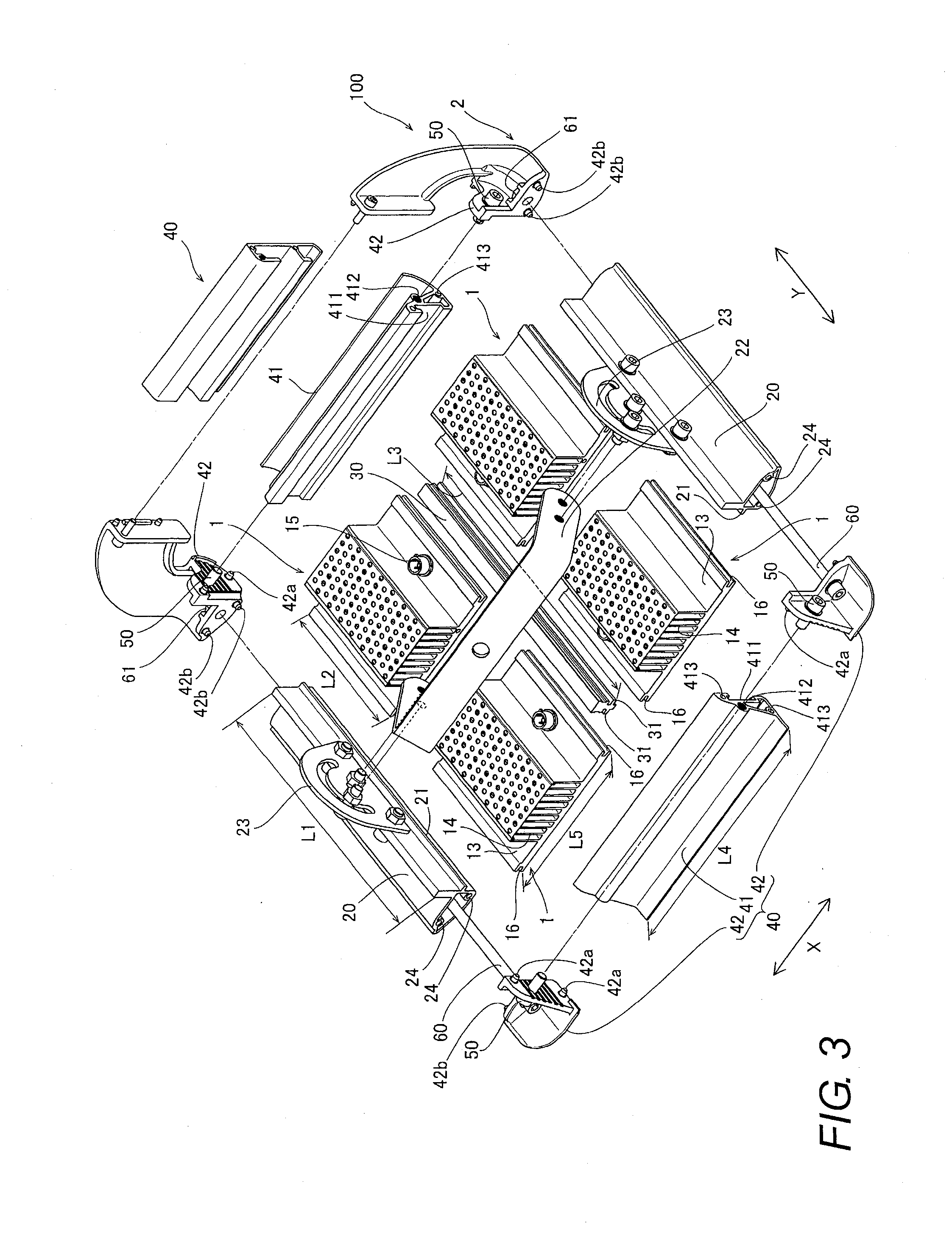
[0025]Referring initially to FIGS. 1 to 6, a lighting device 100 is illustrated in accordance with one embodiment. In the illustrated embodiment, the lighting device 100 is used to light a tunnel.

[0026]As shown in FIGS. 1 and 2, the lighting device 100 mainly includes a lighting unit having a plurality of (four in FIG. 1) light emitting units 1 (e.g., at least one light emitting unit), and a frame 2 sandwiching and supporting outer edges of the lighting unit. In the illustrated embodiment, the lighting unit is formed by the four light emitting units 1 arranged in two rows and in two columns. In the illustrated embodiment, the outer edges of the l...


PUM


Abstract

A lighting device includes a lighting unit and a frame. The lighting unit has at least one light emitting unit with light emitting elements. The frame sandwiches outer edges of the lighting unit to support the lighting unit.

Description

CROSS-REFERENCE TO RELATED APPLICATIONS[0001]This application claims priority to Japanese Patent Application No. 2012-168806 filed on Jul. 30, 2012. The entire disclosure of Japanese Patent Application No. 2012-168806 is hereby incorporated herein by reference.BACKGROUND[0002]1. Field of the Invention[0003]The present invention generally relates to a lighting device. More specifically, the present invention relates to a lighting device in which a light emitting unit is supported by a frame.[0004]2. Background Information[0005]A lighting device in which light emitting components are supported by a frame is well-known (see Japanese Laid-Open Patent Application Publication No. 2012-38532 (Patent Literature 1), for example).[0006]The above-mentioned Patent Literature 1 discloses a lighting device used to light a tunnel. The lighting device has a plurality of LED units (light emitting units) each having a plurality of LED modules, and a box-like main body (frame) to which the LED units a...

Claims


Application Information

Patent Timeline
IPC IPC(8): F21V21/00
CPCF21V21/00F21S2/005F21V15/01F21W2131/101F21V29/763
Inventor LIU, MINGHUI
Owner FUNAI ELECTRIC CO LTD
Why Eureka
Eureka Blog
Learn More