
Vacuum Cleaner

a vacuum cleaner and vacuum chamber technology, applied in the field of vacuum cleaners, can solve the problems of reducing the efficiency of dust separation, inconvenience for users, and limited space in the dust collection unit, and achieve the effect of convenient and fast dust compression operation and convenient emptying of the dust collection container

Inactive Publication Date: 2014-01-23
AB ELECTROLUX
View PDF19 Cites 9 Cited by
  • Summary
  • Abstract
  • Description
  • Claims
  • Application Information

AI Technical Summary

Benefits of technology

The patent describes a new vacuum cleaner design that separates and collects dust effectively and easily empties the container without touching the bottom plate or the dust. The design uses an actuator to move the dust separating device in the container and controls the opening and closing of the bottom plate through an opening and closing arrangement. This allows for smooth emptying of the container without the need for direct contact between the user and the dust. The design also prevents dust from flying up and spilling out with features that minimize the flying up of dust and dust spillage. Overall, the patent describes a solution for effective and robust dust separation, collected and compressed in a bagless vacuum cleaner.

Problems solved by technology

The space in the dust collecting unit is rather limited and is easily filled up by loosely compacted dust.
The dust collecting unit should therefore be emptied frequently which may cause inconvenience to the user.
However, if the dust container is not emptied often enough, the build up of dust in the dust collecting unit will disturb the air flow and cause lowered dust separation efficiency.
A drawback with the system described in WO2009 / 011478A1 is that it requires a further driving unit to compact dust in the dust storage container in addition to the driving unit or motor for generating air suctioning force.
Also, the system comprises many constructional parts, which makes it both expensive and sensitive for failure in one of the parts.
It is a drawback with the described device that the dust cannot be compressed during operation of the vacuum cleaner.

Method used


Image

  • Vacuum Cleaner
  • Vacuum Cleaner
  • Vacuum Cleaner

Examples


Embodiment Construction

[0034]The present invention will now be described more fully with reference to the accompanying drawings, in which example embodiments are shown. However, this invention should not be construed as limited to the embodiments set forth herein. Disclosed features of example embodiments may be combined as readily understood by one of ordinary skill in the art to which this invention belongs. Throughout the following description similar reference numerals have been used to denote similar elements, parts, items or features, when applicable.

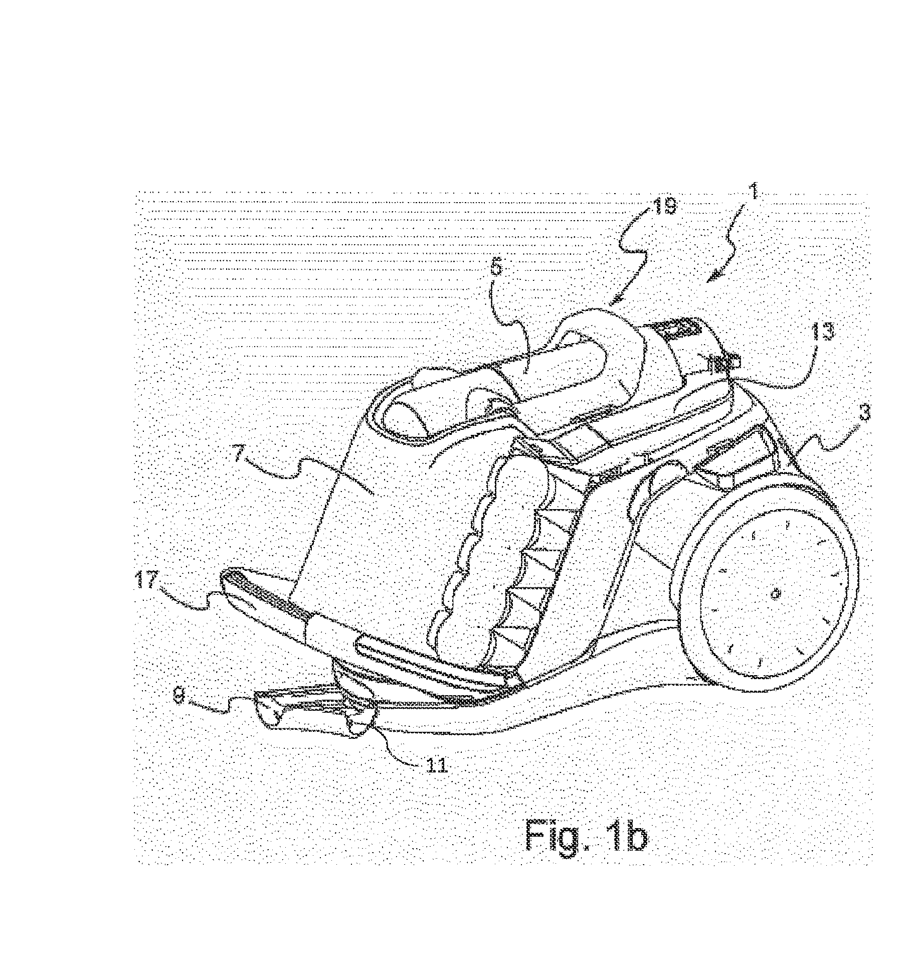
[0035]In FIGS. 1a and 1b a vacuum cleaner 1 according to embodiments are shown. The vacuum cleaner comprises a main body 3, a dust separating device 5 and a dust collecting container 7. A suction motor (not shown) is disposed in the main body for generating a suction force at an air inlet 9. A hose system and nozzle can be connected to the air inlet 9 for performing the cleaning. Basically, any known hose system and nozzle is feasible.

[0036]From the air...


PUM


Abstract

The present invention relates to a vacuum cleaner, and more particularly, to a bagless vacuum cleaner. The vacuum cleaner (1) comprises a dust separating device (5), provided with a dust outlet (29), for separating dust from an incoming air flow, and a dust collecting container (7) being arranged at the dust separating device for receiving dust via the dust outlet from the dust separating device. The dust separating device comprises a first part (5a) and a second part (5b) being releasably connectable to each other, wherein the second part (5b) of the dust separating device is arranged to be movable in the dust collecting container (7) after being released from the first part (5a) of the dust separating device for compressing dust received in the dust collecting container.

Description

TECHNICAL FIELD[0001]The present invention relates to a vacuum cleaner, and more particularly, to a bagless vacuum cleaner. The invention is intended for use particularly but not exclusively in a bagless vacuum cleaner comprising one or more dust separating steps wherein the dust separation takes place in one or more cyclone separation units.BACKGROUND OF THE INVENTION[0002]Generally, a vacuum cleaner includes a suction nozzle for sucking air and dust while the suction nozzle moves along a surface, a main body with a motor and a fan for generating air suctioning force through the suction nozzle and a dust collecting unit.[0003]Particularly in bagless type vacuum cleaners gravity is used to drop dust and other foreign particles in the dust collecting unit. The space in the dust collecting unit is rather limited and is easily filled up by loosely compacted dust. The dust collecting unit should therefore be emptied frequently which may cause inconvenience to the user. However, if the d...

Claims


Application Information

Patent Timeline
IPC IPC(8): A47L9/10
CPCA47L9/10A47L9/108A47L9/1683A47L9/327A47L9/1608A47L9/1691A47L5/362A47L9/1625A47L9/1641A47L9/1658A47L9/19
Inventor HAEGERMARCK, ANDERSMIEFALK, HAKAN
Owner AB ELECTROLUX
Learn More