Spindle drive

Active Publication Date: 2014-01-02
WITTENSTEIN SE
View PDF5 Cites 10 Cited by
  • Summary
  • Abstract
  • Description
  • Claims
  • Application Information

AI Technical Summary

Benefits of technology

The patent describes a lubricating system for a spindle drive, which includes a stationary and a rotating channel system to guide lubricant to the lubricating channel outlet. The rotating channel system is connected to the stationary channel system, allowing lubrication to continue during operation. A transfer space is used between the two channel systems to ensure continuous lubrication, and the system is sealed to prevent lubricant losses. The spindle is connected fixedly to a hollow-shaft rotor, enabling lubrication without dismantling the rotor. The system uses radial channels with a radial directional component of at most 45 degrees. The technical effects of this lubricating system include improved lubrication efficiency, reduced wear and improved performance of the spindle drive.

Problems solved by technology

In particular in the case of spindle drives which are installed in compact linear actuators, relubrication is difficult or impossible, without removal or partial dismantling of the linear actuator or the spindle drive taking place.

Method used


Image

  • Spindle drive
  • Spindle drive
  • Spindle drive

Examples


Embodiment Construction

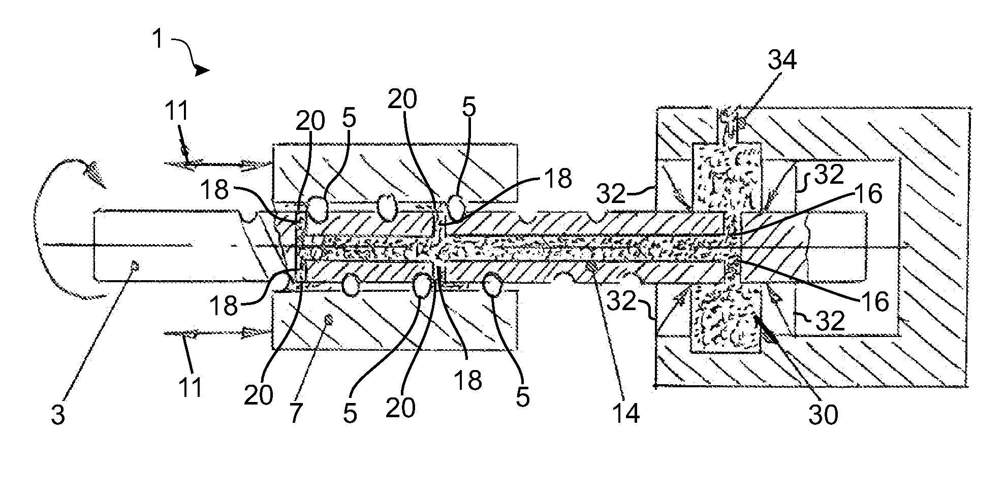
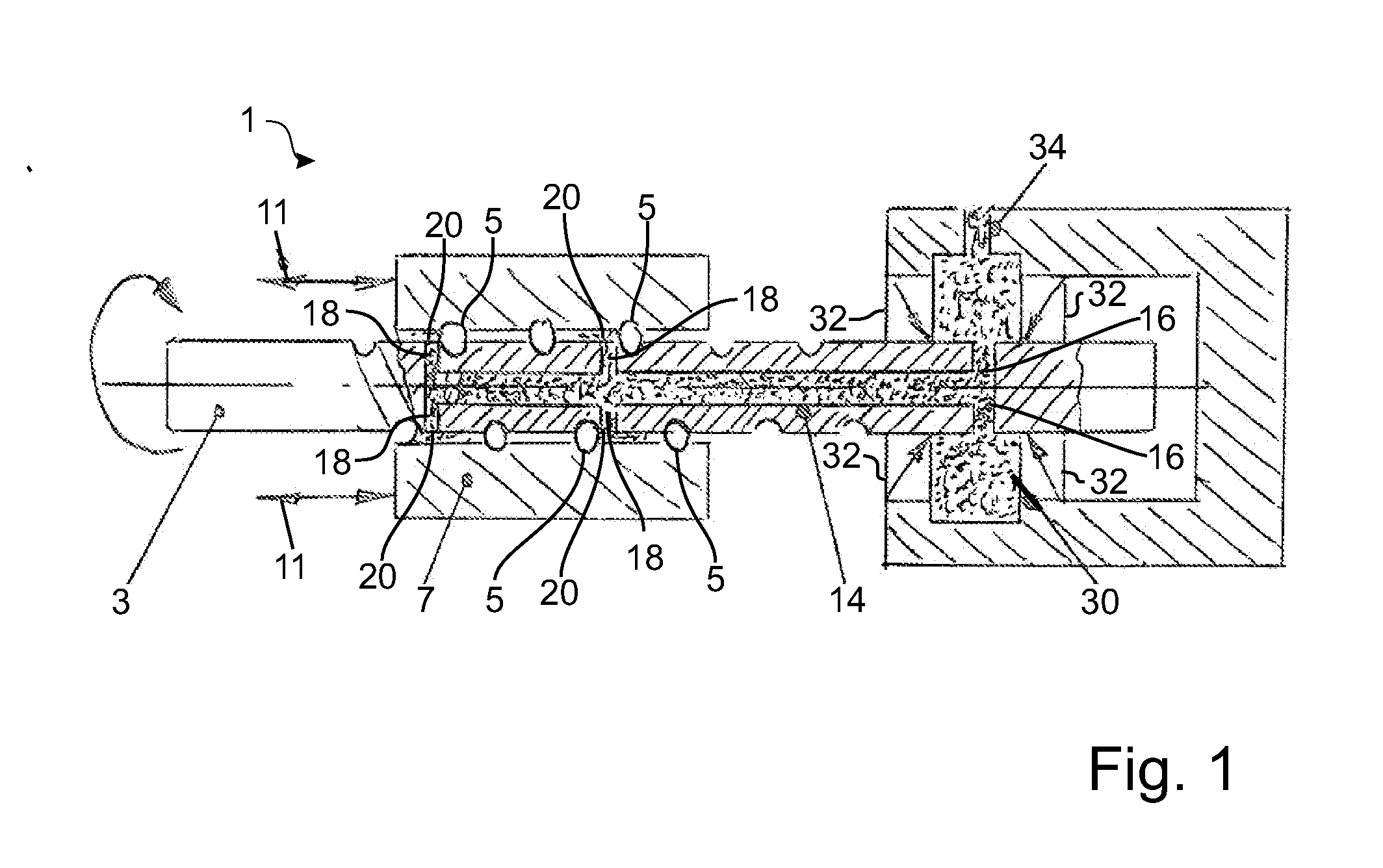
[0021]FIG. 1 shows one embodiment of a spindle drive 1. The spindle drive 1 has a spindle 3 which interacts via rolling bodies 5 with a spindle nut 7. In the embodiment of FIG. 1, the spindle 3 is mounted rotatably, it being provided during operation to drive the spindle 3, in order to achieve an axial movement along the double arrows 11 on the spindle nut 7.

[0022]A rotatable channel system which has a longitudinal channel 14 for lubricant along the center axis of the spindle 3 is provided within the spindle 3. Lubricant is indicated within the lubricant channels in a dotted manner in each case in all drawings, which lubricant is present at least temporarily in the channels during operation. However, the lubricant is generally not a constituent part of the invention.

[0023]The longitudinal channel 14 is supplied with lubricant by first radial lubricating channels 16. The lubricant is guided via the longitudinal channel 14 to second radial lubricating channels 18 which open into lubri...


PUM


Abstract

Spindle drive (1), in particular for a linear actuator, having a spindle (3), a spindle nut (7) which interacts with the spindle (3), and a lubricating channel outlet (20) which opens into an intermediate space between the spindle (3) and the spindle nut (7) for lubricating the spindle (3) and the spindle nut (7), the spindle drive (1) comprising, moreover, a stationary channel system and a rotatable channel system which is connected to the stationary channel system for feeding lubricant to the lubricating channel outlet (20).

Description

BACKGROUND OF THE INVENTION[0001]The invention relates to a spindle drive for a linear actuator.[0002]The prior art discloses spindle drives which are used to convert rotating movements into linear movements or vice versa. In particular in the case of spindle drives which are installed in compact linear actuators, relubrication is difficult or impossible, without removal or partial dismantling of the linear actuator or the spindle drive taking place. Maintenance during running operation is frequently completely ruled out.[0003]The invention is based on the object of improving spindle drives which are known from the prior art; in particular, spindle drives which are installed in linear actuators are to be improved, with the result that simple relubrication is made possible. In particular, relubrication during running operation is to be possible.SUMMARY OF THE INVENTION[0004]The object is achieved by way of a spindle drive comprising a spindle nut which interacts with the spindle, and...

Claims


Application Information

Patent Timeline
IPC IPC(8): F16H25/12
CPCF16H25/12F16H57/043F16H57/0497F16H25/2204Y10T74/18744
Inventor SCHWARZBACH, MICHAEL
Owner WITTENSTEIN SE
Why Eureka
Try Eureka