
Connected vehicle application testing in the laboratory

a connected vehicle and laboratory technology, applied in the direction of traffic control systems, instruments, structural/machine measurement, etc., can solve the problems of difficult integration of complex systems into motor vehicles, radio signals are prone to interference and blockage, and present significant challenges both technological and logistical

Active Publication Date: 2013-12-26
SPIRENT COMM
View PDF8 Cites 39 Cited by
  • Summary
  • Abstract
  • Description
  • Claims
  • Application Information

AI Technical Summary

Benefits of technology

The technology described in this patent allows for the testing of connected vehicle systems by simulating the signals they will receive in operation. This can be useful for testing algorithms, prototypes, and complete systems. The simulation can account for the position of multiple on board units as they move with the vehicles that carry them. The technology can be practiced as a method, device, or computer readable medium that causes a device to practice the method or that, when combined with appropriate hardware, produces the device. Overall, this technology provides a more efficient and effective way to test and develop connected vehicle systems.

Problems solved by technology

Such a radio network, whilst appearing a simple concept on first inspection, presents significant challenges both technological and logistical.
Radio signals are prone to interference and blockage in the types of environments where motor vehicles operate and may have limited range.
Integration of complex systems into motor vehicles is difficult unless conducted during manufacture, so it will take some considerable time to create penetration rates where there are enough connected vehicles to enable associated strategies to be effective.
Test tracks offer only limited scope to cover the vast array of situations to be researched.
On live road networks, the full range of situations cannot be created without disruption or introduction of safety hazards.
Such trials are invariably expensive in terms of provision of physical assets and human resources.
Also, prototype transmitters may fall short of the performance expected of deployable units especially in the areas of transmitter power.
However, such simulations almost never include actual radio network and other hardware and associated sensors and represent a further compromise as a result.

Method used


Image

  • Connected vehicle application testing in the laboratory
  • Connected vehicle application testing in the laboratory
  • Connected vehicle application testing in the laboratory

Examples


Embodiment Construction

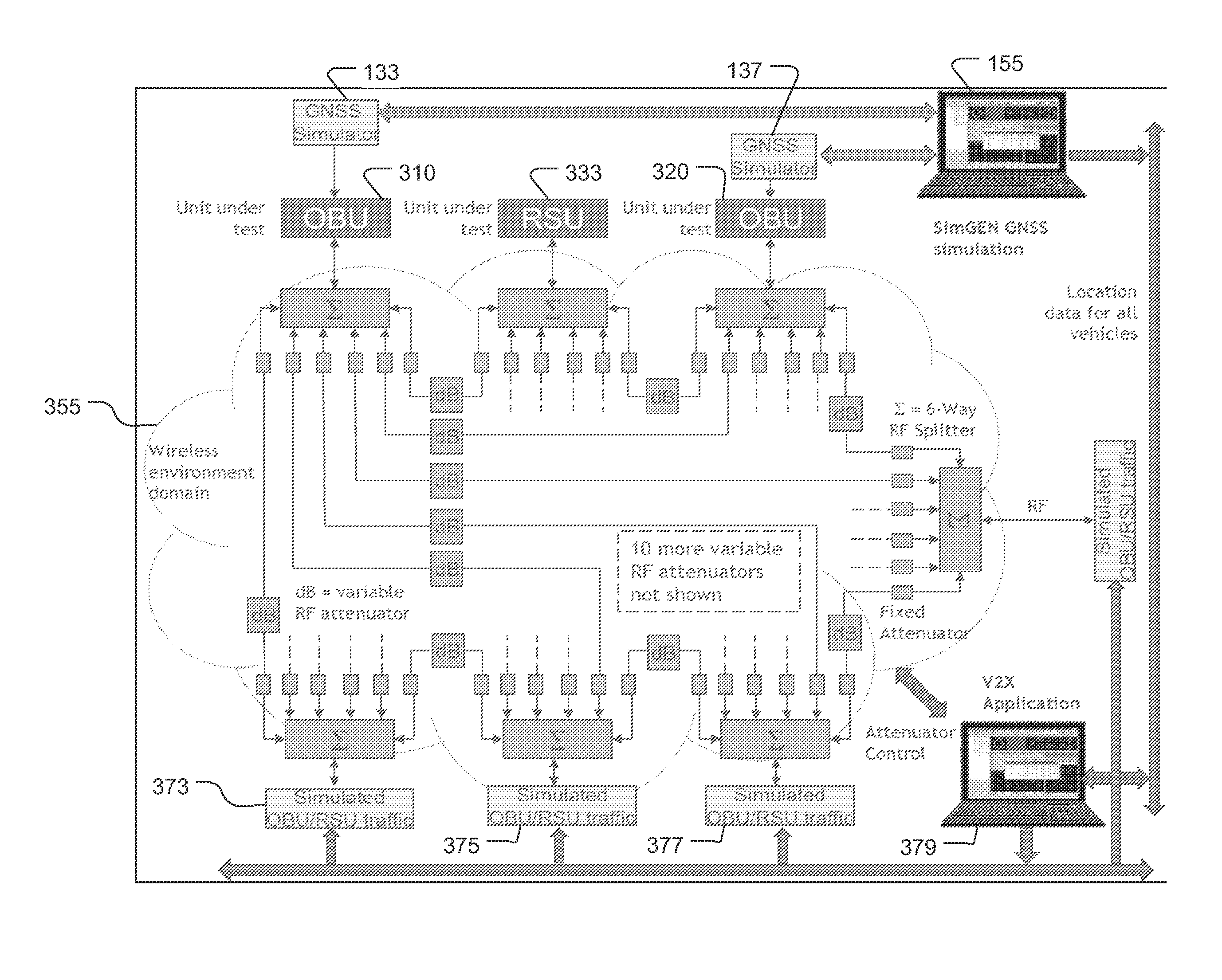
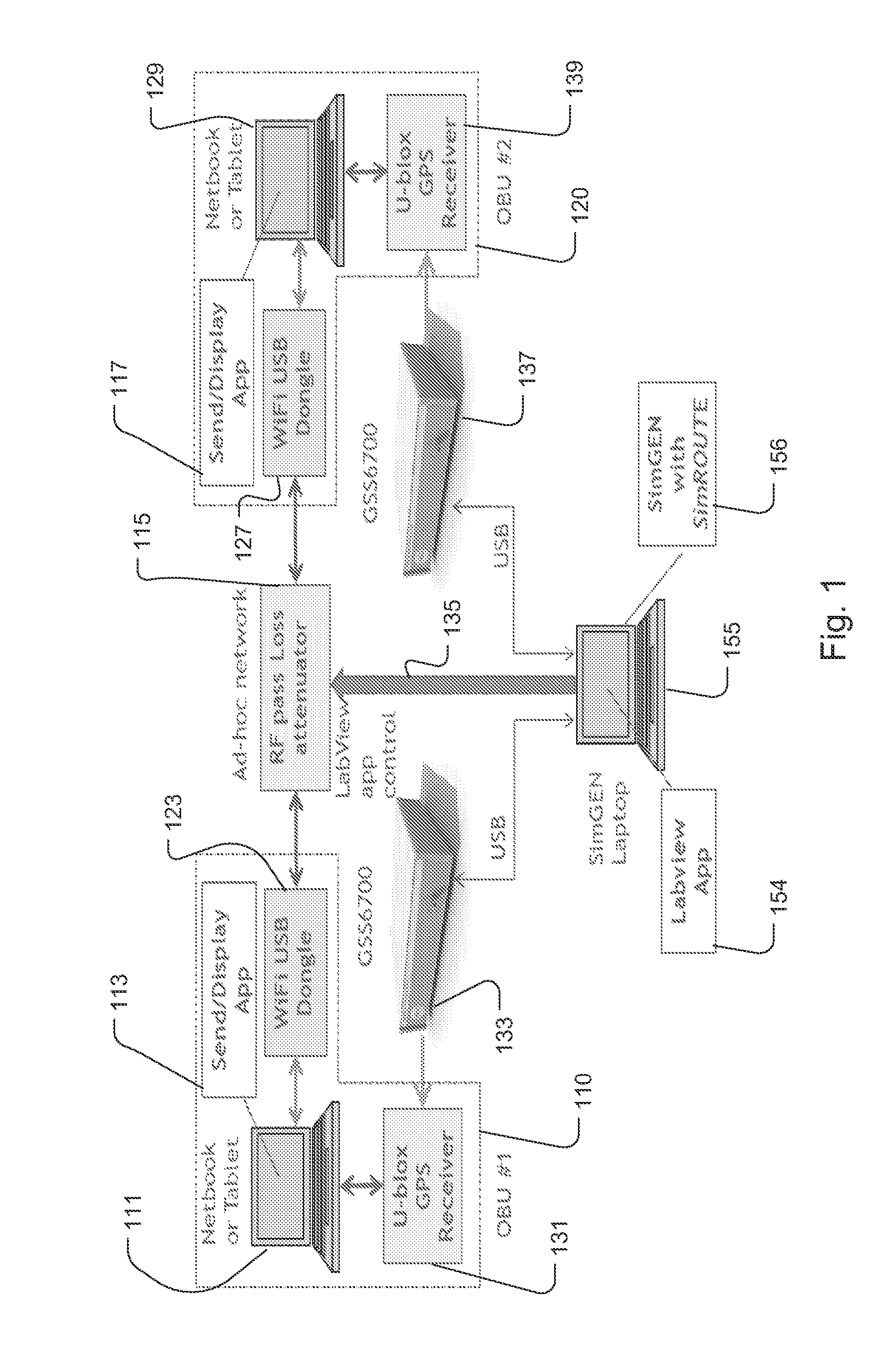
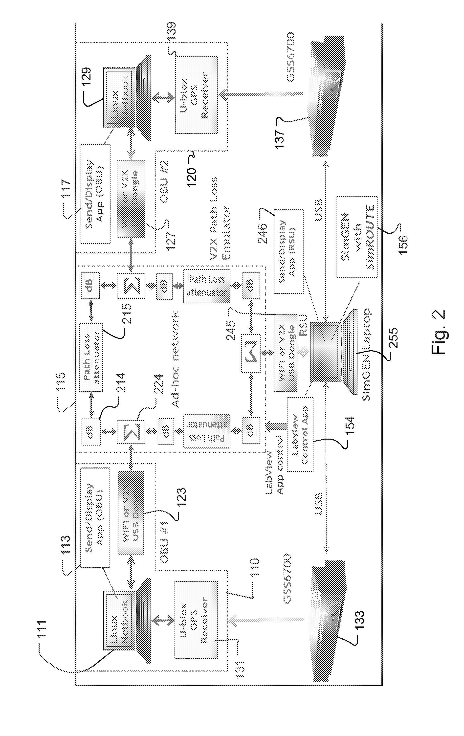
[0016]A detailed description of implementations of the technology disclosed is provided with reference to the FIGS. 1-3.

[0017]The technology disclosed bridges the gap between field trials and pure computer simulation by synthesizing the dynamic radio environment in the laboratory, harnessing the power of computer simulation whilst including in-vehicle hardware and software.

Glossary of Terms

[0018]Connected Vehicle means a vehicle equipped with navigation, proximity and other sensors which may communicate via radio signals in a coordinated way with other similarly equipped vehicles and roadside infrastructure for the purposes of road safety, traffic management, data transfer or similar applications.

[0019]On Board Unit (OBU) means a package of electronics and associated sensors that, when installed in a target vehicle, provide the ‘Connected vehicle’ functionality. Such sensors may include, but not be limited to, GPS, Radar, Lidar, Infra-red and wheel motion.

[0020]Roadside Unit (RSU) m...


PUM


Abstract

The technology disclosed relates to testing of connected vehicle systems. The connections involved are sometimes referred to as Car-2-Car (C2C), Vehicle-to-Vehicle (V2V), Car-2-Infrastructure (C2I), or Vehicle-to-Infrastructure (V2I). More generically, the connections are referred to as C2X and V2X. The technology disclosed provides an over the wire simulation of signals that a system will receive in operation, which allows testing of algorithms, breadboards, prototypes and complete systems. The system simulates the position of multiple on board units as the move with the vehicles that carry them. It attenuates signals between the OBUs and can attenuate signals among the OBUs and other test components, including roadside units and synthetic OBUs. The simulation is can be practiced as a method, a device, or computer readable medium that causes a device to practice the method or that, when combined with appropriate hardware, produces the device.

Description

RELATED APPLICATIONS[0001]This application claims the benefit of U.S. Prov. App. No. 61 / 664,014 filed Jun. 25, 2012, with the same title and inventors as this application, which is hereby incorporated by reference.[0002]This application builds on technologies found in previous applications that could be considered related. The following prior applications are identified. PCT Publication WO 2010 / 093999 A2, published Aug. 19, 2010, “Method and Apparatus for Virtual Desktop OTA [Over the Air]”; U.S. App. No. 12 / 850,986 (unpublished), filed Aug. 5, 2010, “Virtual Drive Test Tool”; and U.S. Pub. 2011 / 0257923 A1, published Oct. 20, 2011. These three previous applications are hereby incorporated by reference.BACKGROUND[0003]1. Field[0004]The technology disclosed relates to testing of connected vehicle systems. The connections involved are sometimes referred to as Car-2-Car (C2C), Vehicle-to-Vehicle (V2V), Car-2-Infrastructure (C2I), or Vehicle-to-Infrastructure (V2I). More generically, the...

Claims


Application Information

Patent Timeline
Patent Type & Authority Applications(United States)
IPC IPC(8): G01M17/007
CPCG01M17/007G08G1/0112G08G1/0116
Inventor BOULTON, PETER GEORGEPOTTLE, JOHN
Owner SPIRENT COMM
Learn More