
Turntable-mounted keypad

a keypad and turntable technology, applied in the field of disk jockeying hardware, can solve the problems of difficult control, difficulty in switching attention, and difficulty in djs to switch back to the computer, and achieve the effect of facilitating the attachment of the keypad to the turntabl

Inactive Publication Date: 2013-12-19
WARD III JOSEPH G
View PDF0 Cites 1 Cited by
  • Summary
  • Abstract
  • Description
  • Claims
  • Application Information

AI Technical Summary

Benefits of technology

The keypad allows DJs to control software seamlessly, reducing performance delays by keeping controls conveniently located and consistent, enhancing the quality and efficiency of DJ performances.

Problems solved by technology

Although the conventional arrangement provides a great deal of flexibility for enhancing musical playback, we have recognized it is also sometimes difficult to control.
When the DJ then needs to control the software, the DJ may find it difficult to switch attention and the position of his or her hands back to the computer.

Method used


Image

  • Turntable-mounted keypad
  • Turntable-mounted keypad
  • Turntable-mounted keypad

Examples


Embodiment Construction

[0031]As used throughout this document, the words “comprising,”“including,” and “having” are intended to set forth certain items, steps, elements, or aspects of something in an open-ended fashion.

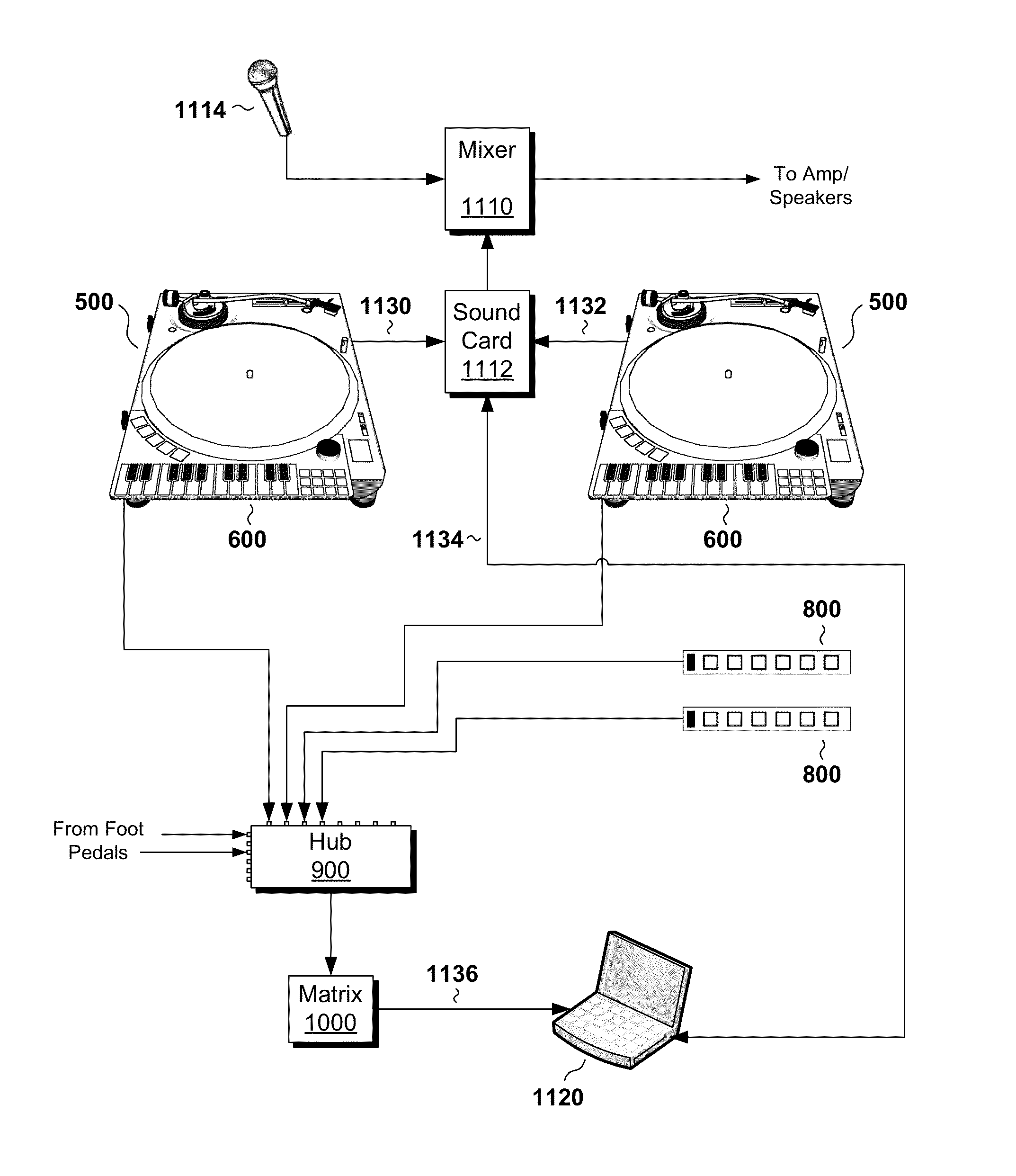
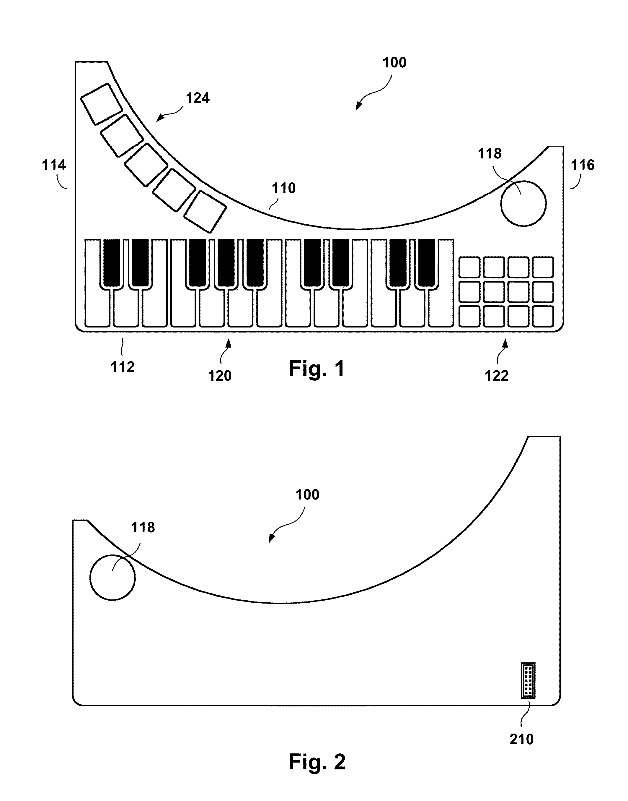
[0032]FIG. 1 shows a keypad circuit board 100 according to an illustrative embodiment of the invention. The keypad circuit board 100 preferably has a top edge 110 in the shape of a circular arc and a straight bottom edge 112. The keypad circuit board 100 preferably has straight sides 114 and 116, which are square with the bottom edge 112. A hole 118 is provided at the upper-right of the keypad circuit board 100.

[0033]The keypad circuit board 100 includes a plurality of keys. These preferably include a first group of keys 120, a second group of keys 122, and a third group of keys 124. The first group of keys 120 is provided in the shape of piano keys, including both white and black keys.

[0034]FIG. 2 is a rear view of the keypad circuit board 100. As shown, the keypad circuit board 100 furthe...


PUM


Abstract

A keypad for controlling software, such as disk jockey (DJ) software, includes a plurality of keys, each key being programmable for issuing any desired, predefined sequence of keystrokes and / or mouse commands in response to the key being pressed. At least some of the keys are laid out in a piano-style format, with those keys being programmed to direct the software to produce musical notes. The keypad is constructed to be attached to a phonograph turntable by engaging with physical features on the turntable. The keypad has a top surface that has a rounded edge that runs concentrically with the turntable's platter. It also has a straight edge, overhanging the side of the turntable, where the piano style keys are positioned. When used by a DJ, the keypad greatly simplifies the task of simultaneously operating the turntable and the DJ software.

Description

CROSS-REFERENCES TO RELATED APPLICATIONS[0001]This application is a continuation of U.S. application Ser. No. 12 / 868,713, filed Aug. 25, 2010 (now issued as U.S. Pat. No. 8,514,106), which in turn claims the benefit of U.S. Provisional Application No. 61 / 236,916, filed Aug. 26, 2010, the contents and teachings of which are hereby incorporated by reference in their entirety.STATEMENT REGARDING FEDERALLY SPONSORED RESEARCH OR DEVELOPMENT[0002]Not Applicable.NAMES OF PARTIES TO A JOINT RESEARCH AGREEMENT[0003]Not ApplicableREFERENCE TO A “SEQUENCE LISTING,” A TABLE, OR A COMPUTER PROGRAM LISTING APPENDIX[0004]Not Applicable.BACKGROUND OF THE INVENTION[0005]1. Field of the Invention[0006]This invention relates generally to disk jockeying hardware, and, more particularly, to devices used by disk jockeys in connection with computers to produce sounds, sound effects, and other effects.[0007]2. Description of Related Art[0008]Recent developments in digital audio have brought many advances t...

Claims


Application Information

Patent Timeline
Patent Type & Authority Applications(United States)
IPC IPC(8): G10H1/34
CPCG10H1/346G10H1/0091G10H1/32G10H1/34G10H1/348G10H2210/241
Inventor WARD, III, JOSEPH G.
Owner WARD III JOSEPH G
Learn More