
Method of shoot-through generation for modified sine wave z-source, quasi-z-source and trans-z-source inverters

a technology of z-source and quasi-z-source inverters, which is applied in the direction of ac-dc conversion, electrical equipment, power conversion systems, etc., can solve the problems of not being able to increase voltage, complex control algorithms, and low-frequency sine signals cannot pass through high-frequency pulse transformers

Active Publication Date: 2013-12-12
OU UBIK SOLUTIONS
View PDF1 Cites 10 Cited by
  • Summary
  • Abstract
  • Description
  • Claims
  • Application Information

AI Technical Summary

Benefits of technology

The patent text describes the different states of a Z-source, quasi-Z-source, and trans-Z-source inverter, which are called zero, freewheeling, active, and shoot-through. The zero state is when all the switching elements are turned on simultaneously, creating a short circuit. The freewheeling state is when all the switching elements are turned off simultaneously, and no current is generated. The active state occurs when only one switching element is turned on in each bridge arm, and current is generated. The shoot-through state occurs when all the switching elements in a bridge arm or all the switching elements of the entire inverter are turned on simultaneously. The patent text also describes three methods for generating the shoot-through state: during the freewheeling state or during the zero state.

Problems solved by technology

The disadvantages of sine wave modulation are its rather complicated control algorithm and the fact that low-frequency sine signals cannot pass through a high-frequency pulse transformer in applications requiring galvanic insulation.
The disadvantage of this method is that the voltage cannot be increased.
The disadvantage of the described solution is that it applies only to sine wave modulation and does not determine the methods for shoot-through generation.
The disadvantage of the inverter is that it does not enable to generate freewheeling, zero or shoot-through states.

Method used


Image

  • Method of shoot-through generation for modified sine wave z-source, quasi-z-source and trans-z-source inverters
  • Method of shoot-through generation for modified sine wave z-source, quasi-z-source and trans-z-source inverters
  • Method of shoot-through generation for modified sine wave z-source, quasi-z-source and trans-z-source inverters

Examples


Embodiment Construction

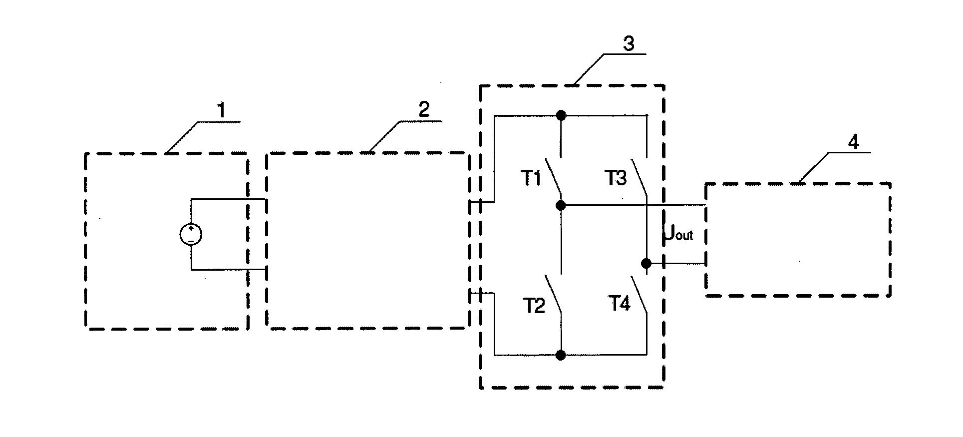
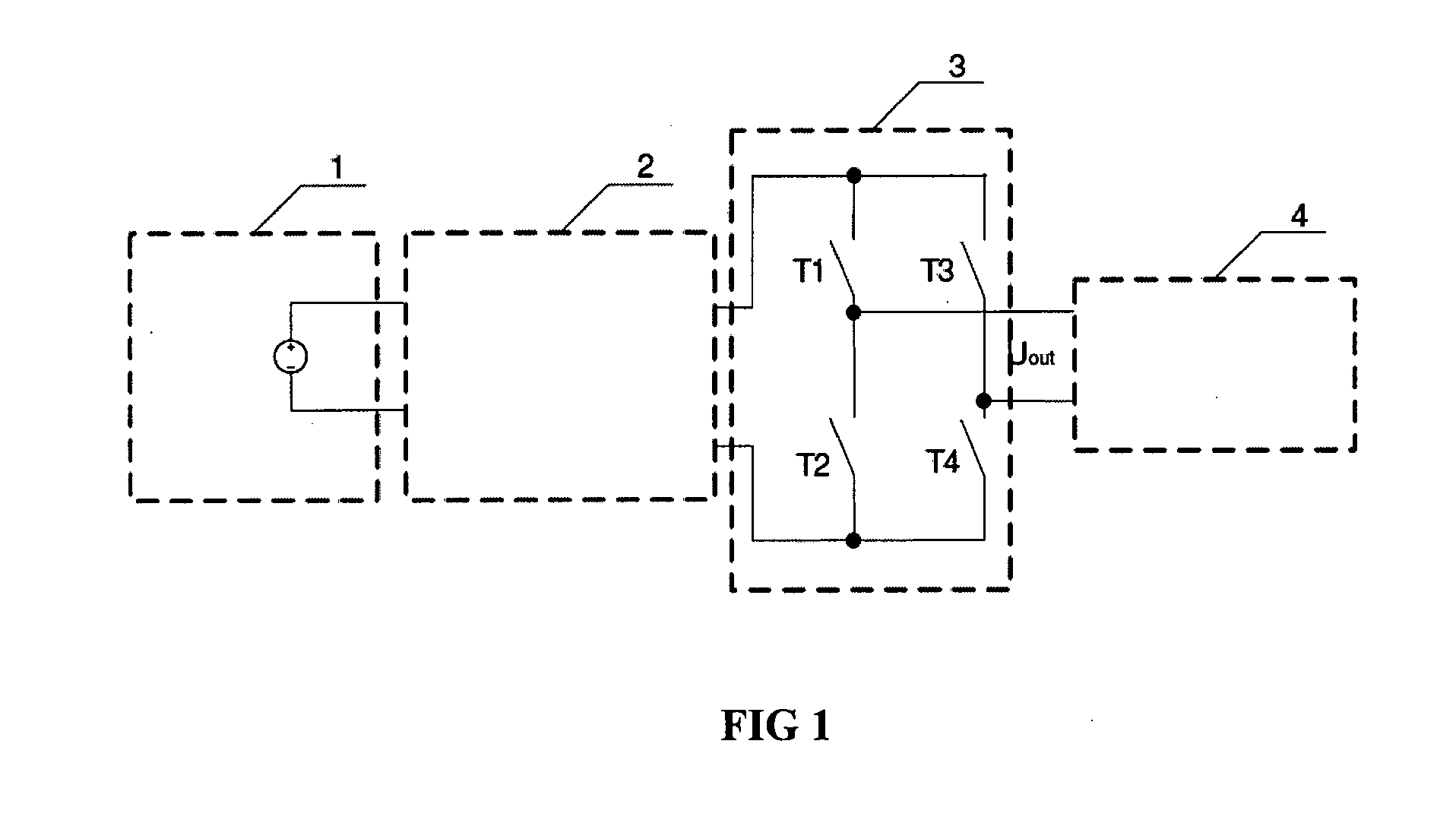
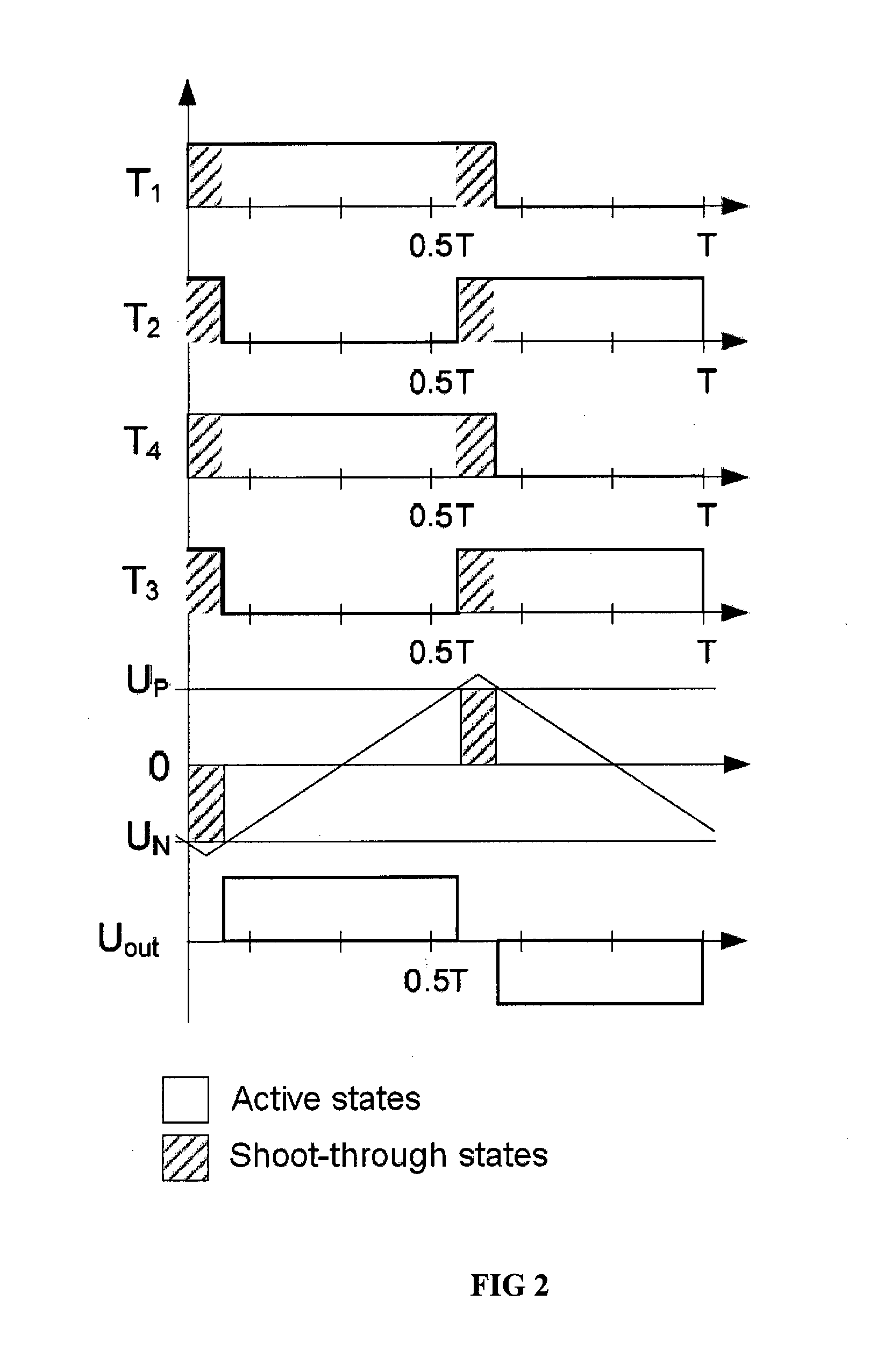
[0023]The principle of the invention is described on the basis of a single-phase inverter. The voltage from the input voltage source (1) is directed through the Z-source, quasi-Z-source or trans-Z-source circuit (2) into a single- or multi-phase inverter (3). The inverter (3) consists of switching elements T1, T2, T3 and T4 (the inverter may also be a multi-phase one). The inverter can be controlled using either the modified sine wave pulse-width modulation (PWM) or phase-shift modulation (PSM) method. A transformer, an AC motor, an AC load, etc., are connected to the output of the inverter (3). Zero states and shoot-through states are distributed across the period (T) in a way that the number of higher harmonics is minimal in the output voltage of the inverter. To reduce the switching and conductivity losses, the number of shoot-through states per switching period is limited to two and the shoot-through current is distributed equally across the transistors of both arms of the inver...


PUM


Abstract

This invention belongs into the field of power electronics and semiconductor converter control and pertains to the method of shoot-through generation for modified sine wave Z-source, quasi-Z-source and trans-Z-source inverters. The inverter can be controlled using either the modified sine wave pulse-width modulation or phase-shift modulation method. There are three methods for shoot-through generation in the case of modified sine wave control: by overlapping active states, during the freewheeling state and during the zero state.

Description

TECHNICAL FIELD[0001]This invention belongs in the field of power electronics and semiconductor converter control and pertains to the methods of shoot-through generation for modified sine wave Z-source, quasi-Z-source and trans-Z-source inverters.BACKGROUND ART[0002]Z-source, quasi-Z-source and trans-Z-source inverters are new DC / AC (voltage) converters in power electronics. These make it possible to both increase and decrease input voltage without additional switching elements. These converters consist of an LC circuit (of Z-source, quasi-Z-source or trans-Z-source-type) and a single-phase or multi-phase inverter (FIG. 1). The voltage is increased by a specific shoot-through state that is generated by turning on the switching elements of one bridge arm of the inverter simultaneously. In this case, the energy of the magnetic field is accumulated in the chokes of LC circuits without short-circuiting the capacitors during the shoot-through. The accumulated energy is used to increase t...

Claims


Application Information

Patent Timeline
Patent Type & Authority Applications(United States)
IPC IPC(8): H02M7/523
CPCH02M7/523H02M7/4826
Inventor VINNIKOV, DMITRIJALAKAS, TANELROASTO, INDREKAGABUS, HANNESTAMMET, KRISTI
Owner OU UBIK SOLUTIONS
Learn More