
Bezel for a cover or platter for a data reader in a checkout station

a data reader and checkout station technology, applied in the direction of instruments, burglar alarm mechanical actuation, electromagnetic radiation sensing, etc., can solve the problems of reducing the effectiveness of the deactivation system, reducing the range of magnetic field, and not providing item security against th

Active Publication Date: 2013-12-12
DATALOGIC ADC
View PDF0 Cites 13 Cited by
  • Summary
  • Abstract
  • Description
  • Claims
  • Application Information

AI Technical Summary

Benefits of technology

The patent text describes a system for preventing theft in retail checkout and inventory control environments. The system uses EAS tags that can be deactivated or removed from the articles being tagged. The deactivation process involves using a coil structure to generate a magnetic field that makes the tag "inactive" and no longer responsive to incident energy applied thereto. The system can be integrated into existing barcode scanners and weigh scales, providing both barcode scanning and EAS tag deactivation in a single device. The technical effect of this system is to enhance security and prevent theft at retail checkout and inventory control counters.

Problems solved by technology

Though barcodes provide for rapid and accurate item identification at checkout, the barcodes do not provide for item security against theft.
Unfortunately, the stainless steel platter may reduce the effectiveness of the deactivation system.
For example, the stainless steel platter can create a closed loop (around the lower window) that interferes with the magnetic pulse generated by the deactivation system, attenuating the range of the magnetic field so that operation of the deactivation system becomes degraded and / or inconsistent.
The failure to deactivate an EAS tag can result in undesirable false alarms from the EAS system.

Method used


Image

  • Bezel for a cover or platter for a data reader in a checkout station
  • Bezel for a cover or platter for a data reader in a checkout station
  • Bezel for a cover or platter for a data reader in a checkout station

Examples


Embodiment Construction

[0027]With reference to the above-listed drawings, this section describes particular embodiments and their detailed construction and operation. The embodiments described herein are set forth by way of illustration only and not limitation. It should be recognized in light of the teachings herein that other embodiments are possible, variations can be made to the embodiments described herein, and there may be equivalents to the components, parts, or steps that make up the described embodiments.

[0028]For the sake of clarity and conciseness, certain aspects of components or steps of certain embodiments are presented without undue detail where such detail would be apparent to those skilled in the art in light of the teachings herein and / or where such detail would obfuscate an understanding of more pertinent aspects of the embodiments.

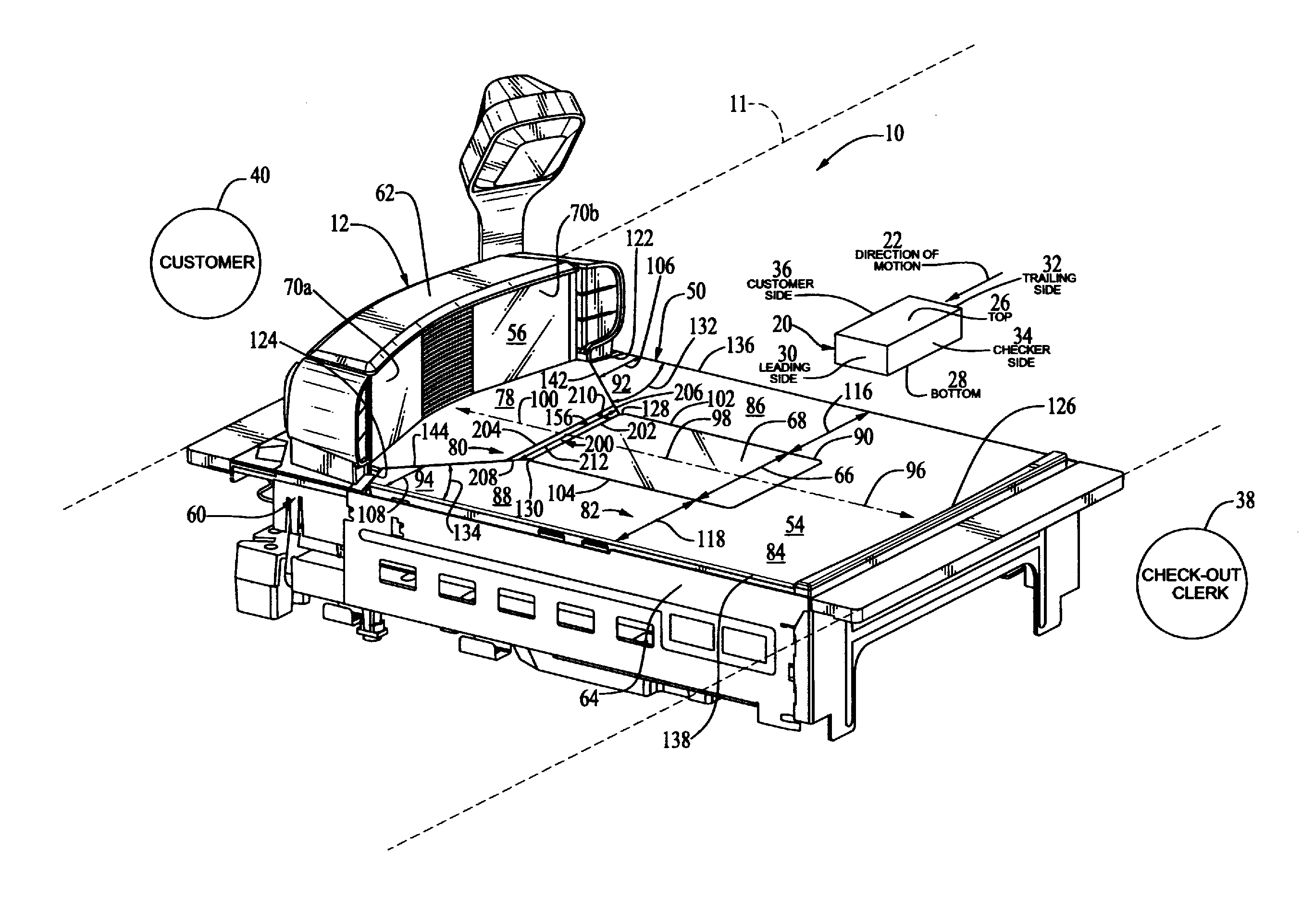
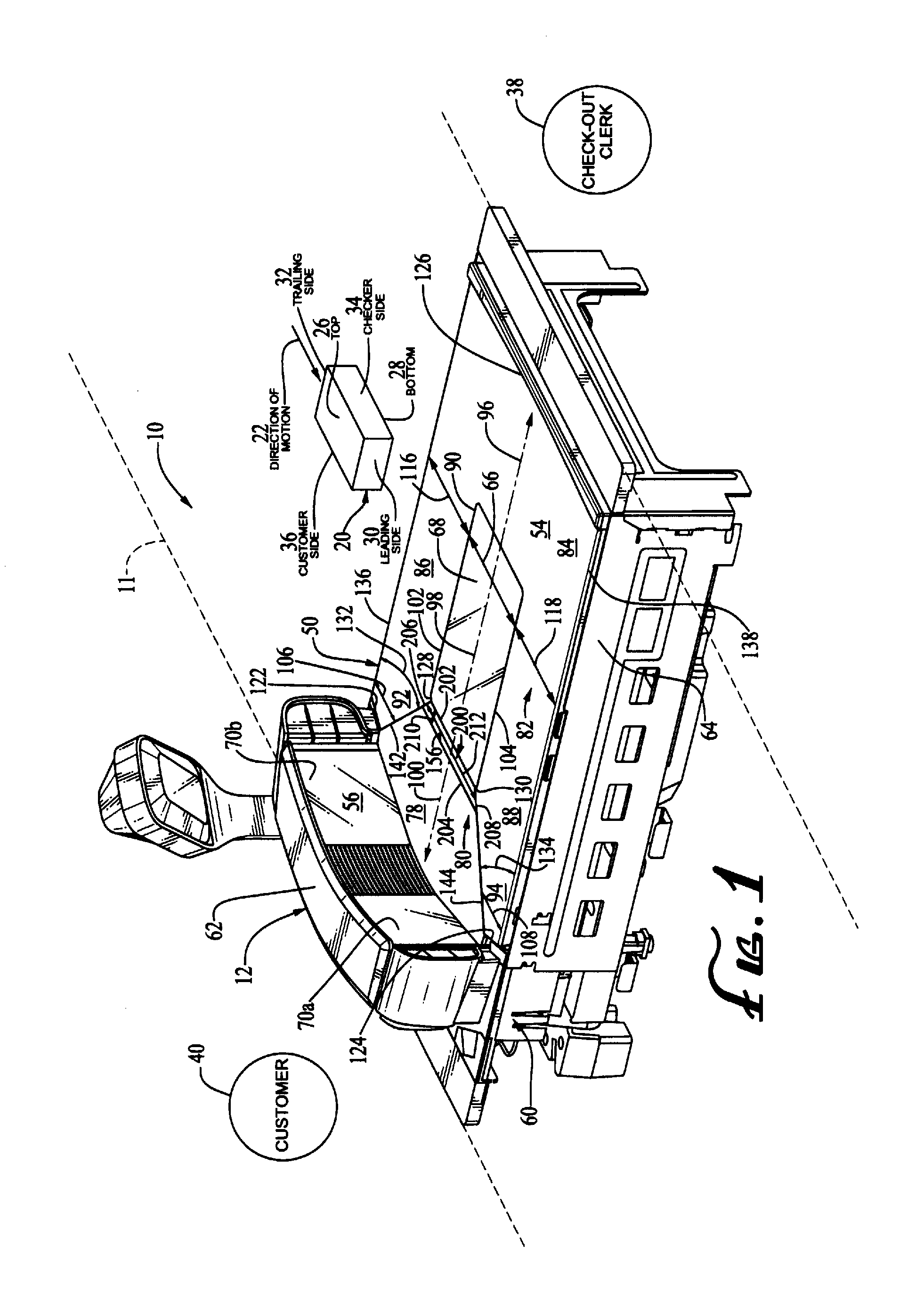
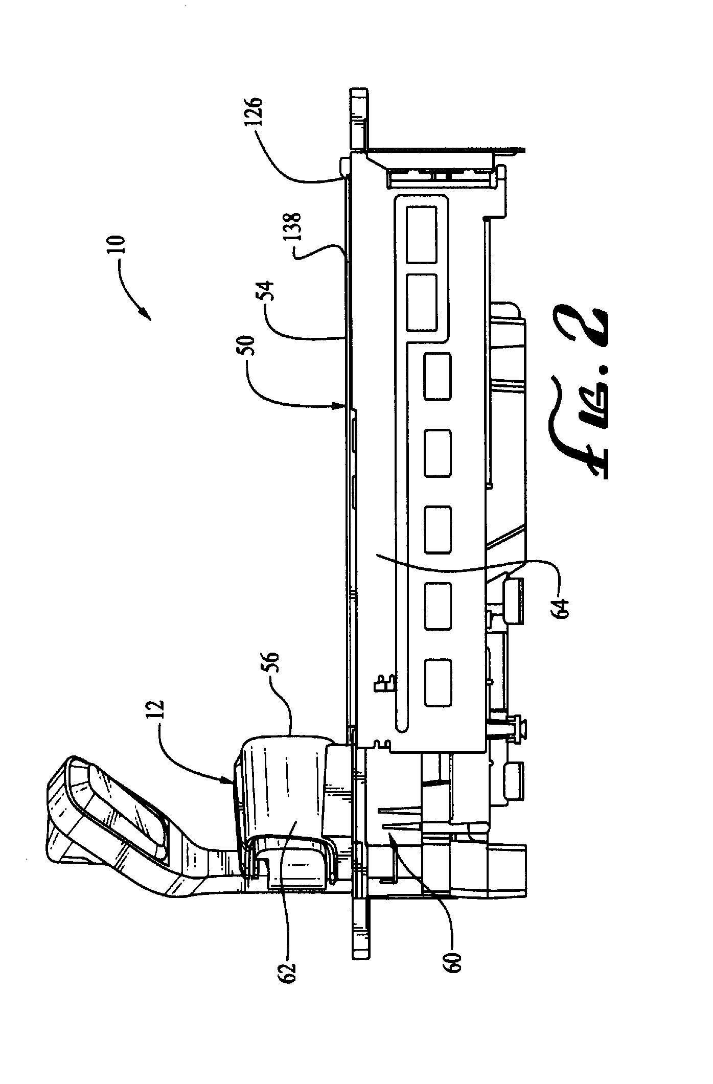
[0029]FIG. 1 illustrates a checkout station 10 having a counter 11 and an optical code reader 12 with a read region or view volume through which items 20 may...


PUM


Abstract

A checkout station includes an optional scale for weighing items; a composite cover or weigh platter supported by the scale, wherein the cover has a lower surface with a lower window having a horizontal perimeter, an upper surface including an upper window positioned transversely to the lower surface, a metallic plate surrounding a portion of the horizontal perimeter of the lower window, the metallic plate spaced apart proximal end sections, and a nonmetallic bezel positioned between the lower window and the upper surface and positioned between the spaced apart proximal end sections of the metallic plate; one or more imagers for obtaining views of an item within a viewing volume bounded by the lower and upper surfaces; and a surveillance tag deactivation system for deactivating an electronic surveillance tag in proximity to the viewing volume.

Description

RELATED APPLICATIONS[0001]This application claims priority from U.S. Provisional Patent Application No. 61 / 657,732, filed Jun. 8, 2012, which is herein incorporated by reference.BACKGROUND[0002]The field of the present disclosure relates generally to checkout stations for data capture and, more particularly but not exclusively, to such checkout stations that may employ a weigh scale adapted for use with electronic article surveillance (EAS) systems. In both retail checkout and inventory control environments, items are typically provided with readable optical codes such as ID barcode labels (e.g., UPC labels), or stacked and 2D code labels (e.g., PDF 417 or Data matrix). Although there are different types of these optical labels, for the purpose of this description, the terms barcodes and optical codes may be used interchangeably.[0003]Data reading devices such as barcode scanners and RFID readers are provided at the checkout station to read the optical codes and obtain the data cont...

Claims


Application Information

Patent Timeline
IPC IPC(8): G08B13/24G06K7/10G06V30/224
CPCG08B13/246G06K7/10821G06K7/1096
Inventor SHEARIN, ALANTHOMPSON, RYAN B.NEWMAN, DAVIDROBSON, JEFF T.
Owner DATALOGIC ADC
Learn More