Surface light source device and liquid crystal display device

a light source device and liquid crystal display technology, applied in the direction of instrumentation, lighting and heating apparatus, planar/plate-like light guides, etc., can solve the problems of large amount of unnecessary light, narrow color gamut of white leds, and reduced light utilization efficiency, so as to suppress the intensity irregularity of light emitted

Active Publication Date: 2013-12-05
MITSUBISHI ELECTRIC CORP
View PDF27 Cites 21 Cited by
  • Summary
  • Abstract
  • Description
  • Claims
  • Application Information

AI Technical Summary

Benefits of technology

The present invention introduces a small surface light source device that minimizes the unevenness of light emitted from different angular intensity distributions.

Problems solved by technology

For that reason, white LEDs have the problem of a narrow color gamut.
If the color filters have narrow wavelength transmission bands, however, then their light utilization efficiency is reduced.
The reason is that there is a large amount of unnecessary light that is not used by the liquid crystal display element of the liquid crystal display device.
Further problems also arise: the brightness of the display surface of the liquid crystal display element is reduced and the power consumption of the liquid crystal display device is increased.
If a color filter with a narrow wavelength bandwidth is used to increase the purity in the desired 630-640 nm wavelength band, the problem arises that the amount of light transmitted is greatly reduced.
Accordingly, the problem of sharply reduced brightness arises.
If light sources having different angular intensity distributions are used, there will be irregularities in the spatial intensity distributions of the colors on the display surface of the liquid crystal display element.

Method used


Image

  • Surface light source device and liquid crystal display device
  • Surface light source device and liquid crystal display device
  • Surface light source device and liquid crystal display device

Examples


first embodiment

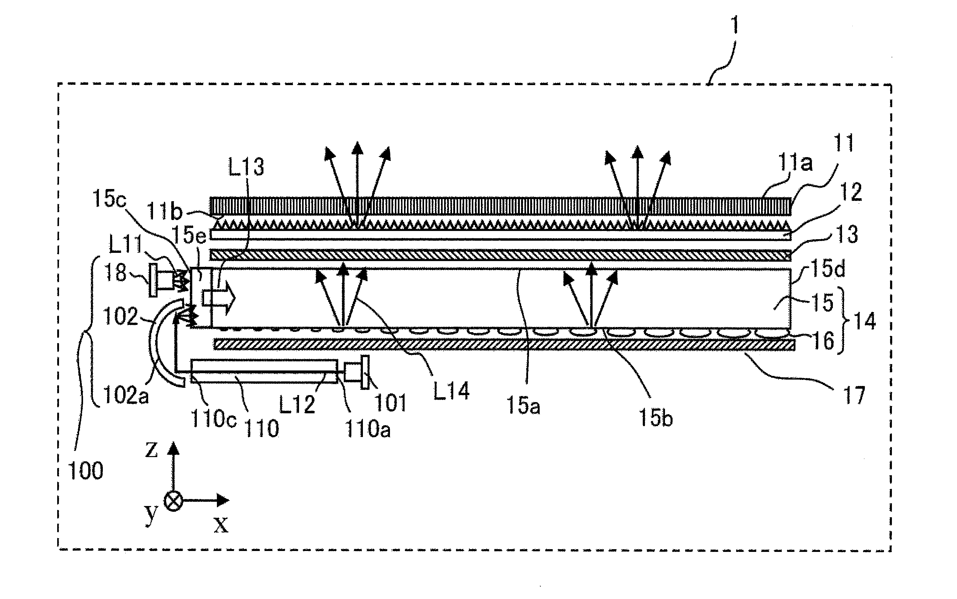
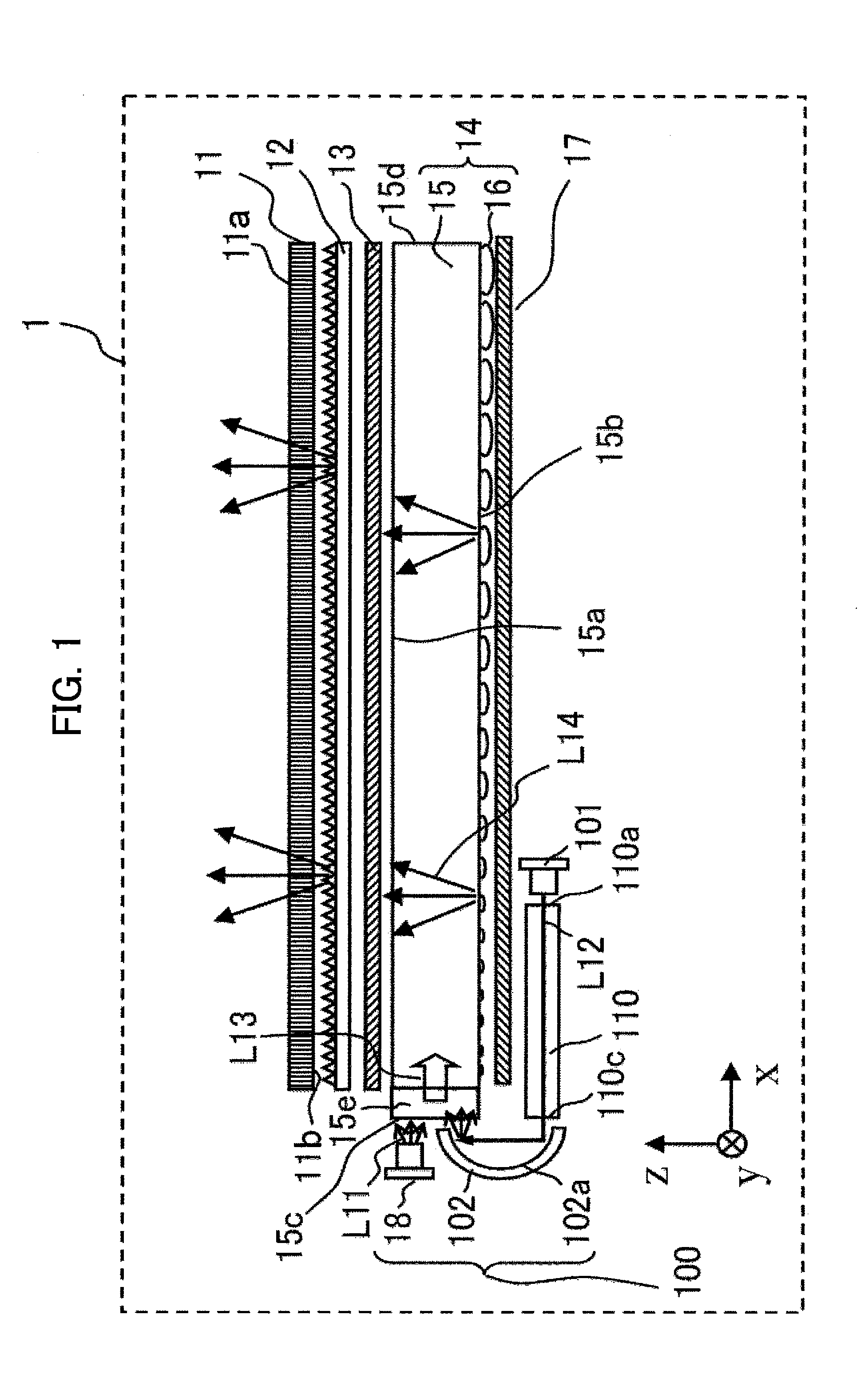
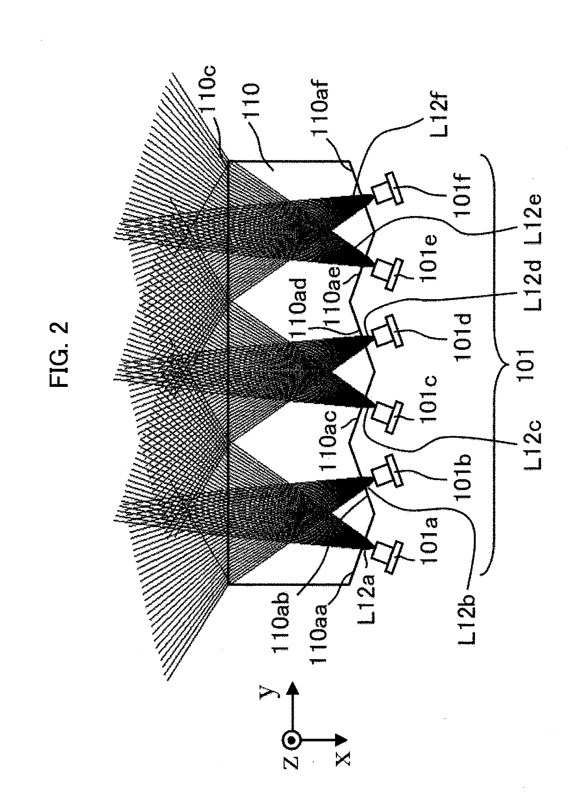
[0034]FIG. 1 is a diagram schematically showing the structure of a liquid crystal display device 1 (including a surface light source device 100) according to a first embodiment. FIG. 2 is a diagram schematically showing the structure of the angular intensity distribution shaping member 110 shown in FIG. 1. FIG. 3 is a diagram showing the light incidence surface 110a of the angular intensity distribution shaping member 110 in greater detail.

[0035]The liquid crystal display device 1 is a transmissive liquid crystal display device including a liquid crystal display element (hereinafter, ‘liquid crystal panel’) 11 having a rectangular display surface 11a and an opposite back surface 11b. For ease of description, the xyz axes of a Cartesian coordinate system are shown in the drawings. In the following description, the short-side direction of the display surface 11a of the liquid crystal panel 11 is the y-axis direction (the direction perpendicular to the plane of the drawing sheet in FIG...

second embodiment

[0111]FIG. 9 is a diagram schematically showing the structure of a liquid crystal display device 2 (including a surface light source device 200) according to a second embodiment. In place of the angular intensity distribution shaping member 110 in the first embodiment, the surface light source device 200 according to the second embodiment includes an angular intensity distribution shaping member 210 having a different shape. In place of the cylindrical mirror 102 in the first embodiment, the surface light source device 200 according to the second embodiment includes a cylindrical mirror 202 having a different shape. The cylindrical mirror 202 functions as a light-path changing member. Components identical to components in the first embodiment shown in FIG. 1 will be denoted by the same reference characters, and descriptions of those components will be omitted. Of the components in the second embodiment shown in FIG. 9, the identical components are the liquid crystal panel 11, optica...

third embodiment

[0172]FIG. 13 is a diagram schematically showing the structure of a liquid crystal display device 3 (including a surface light source device 400) according to a third embodiment. The surface light source device 400 according to the third embodiment includes, instead of the angular intensity distribution shaping member 210 in the second embodiment, an angular intensity distribution shaping member 310 of a different shape. Components identical to components shown in FIG. 1 in the first embodiment or FIG. 9 in the second embodiment will be denoted by the same reference characters, and descriptions of those components will be omitted. Of the components of the third embodiment shown in FIG. 13, the identical components are the liquid crystal panel 11, optical sheets 12, 13, surface emitting light guide plate 15, optical microelements 16, light reflecting sheet 17, first light source 18, and cylindrical mirror 202.

[0173]FIG. 14 is a diagram showing the structure of the angular intensity d...


PUM


Abstract

An angular intensity distribution shaping member includes a first surface for receiving a light beam emitted from a light source, the first surface having a length in a width direction that is longer than that in a thickness direction; second surfaces forming a plate-shaped light path on which the light beam incident from the first surface propagates by total reflection, the second surfaces including at least one adjustment surface for spreading a full angle of an angular intensity distribution, in the width direction, of the light beam incident from the first surface so that the full angle becomes wider than that of the angular intensity distribution of the light beam just after emission from the light source; and a third surface through which the light beam exits, the full angle of its angular intensity distribution in the width direction having been widened by the at least one adjustment surface.

Description

TECHNICAL FIELD[0001]The present invention relates to a surface light source device having a planar light emitting surface, and to a liquid crystal display device having a surface light source device and a liquid crystal panel.BACKGROUND ART[0002]The liquid crystal display element in a liquid crystal display device does not emit light itself. Liquid crystal display devices therefore have a backlight disposed behind the liquid crystal display element as a light source to illuminate the liquid crystal display element. CCF (Cold Cathode Fluorescent) lamps, in which the inner wall of a glass tube is coated with a phosphor and from which white light can be obtained, have been the leading type of light source for backlight use. With the recent striking improvements in LED (Light Emitting Diode) performance, however, the demand for backlights using LED light sources has been rapidly expanding.[0003]Among the devices referred to as LEDs there are monochromatic LEDs and white LEDs. A monochr...

Claims


Application Information

Patent Timeline
IPC IPC(8): F21V8/00
CPCG02B6/0011G02B6/0028G02B6/0036G02B6/0061G02B6/0076G02F1/133615
Inventor NISHITANI, RENANAKANO, NAMIKAGAWA, SHUICHIKUWATA, MUNEHARUKOJIMA, KUNIKO
Owner MITSUBISHI ELECTRIC CORP
Why Eureka
Try Eureka