Portable device and peripheral extension dock

a technology of portable devices and extension docks, which is applied in the direction of electrical apparatus casings/cabinets/drawers, climate sustainability, instruments, etc., can solve the problems of increasing power consumption and reducing the usage time of portable devices

Active Publication Date: 2013-12-05
HTC CORP
View PDF3 Cites 19 Cited by
  • Summary
  • Abstract
  • Description
  • Claims
  • Application Information

AI Technical Summary

Benefits of technology

The invention is related to a technology for connecting electronic devices with external devices using a 1-wire data path. The technology includes a detection pin and an interrupt pin on the processor, which are connected to the 1-wire data path. The processor can detect the status of the connected device using the detection pin and interrupt it using the interrupt pin. This technology allows for easy connection and communication with external devices using a simple 1-wire data path. Another embodiment of the invention includes an extension device that connects to the electronic device using a connector port and a controller, which can detect and interrupt devices connected to the extension device. The extension device simplifies the connection process by providing pre-configured connectors and an interrupt signal. The technical effects of this technology include improved convenience and efficiency in connecting external devices and simplifying the process of device-to-device communication.

Problems solved by technology

However, even if portable devices do not connect to a 1-wire device, the portable device still must poll the 1-wire bus.
Thus, power consumption is increased, affecting limited battery power, thereby decreasing the usage time of the portable device.

Method used


Image

  • Portable device and peripheral extension dock
  • Portable device and peripheral extension dock
  • Portable device and peripheral extension dock

Examples


Embodiment Construction

[0016]The following description is of the best-contemplated mode of carrying out the invention. This description is made for the purpose of illustrating the general principles of the invention and should not be taken in a limiting sense. The scope of the invention is best determined by reference to the appended claims.

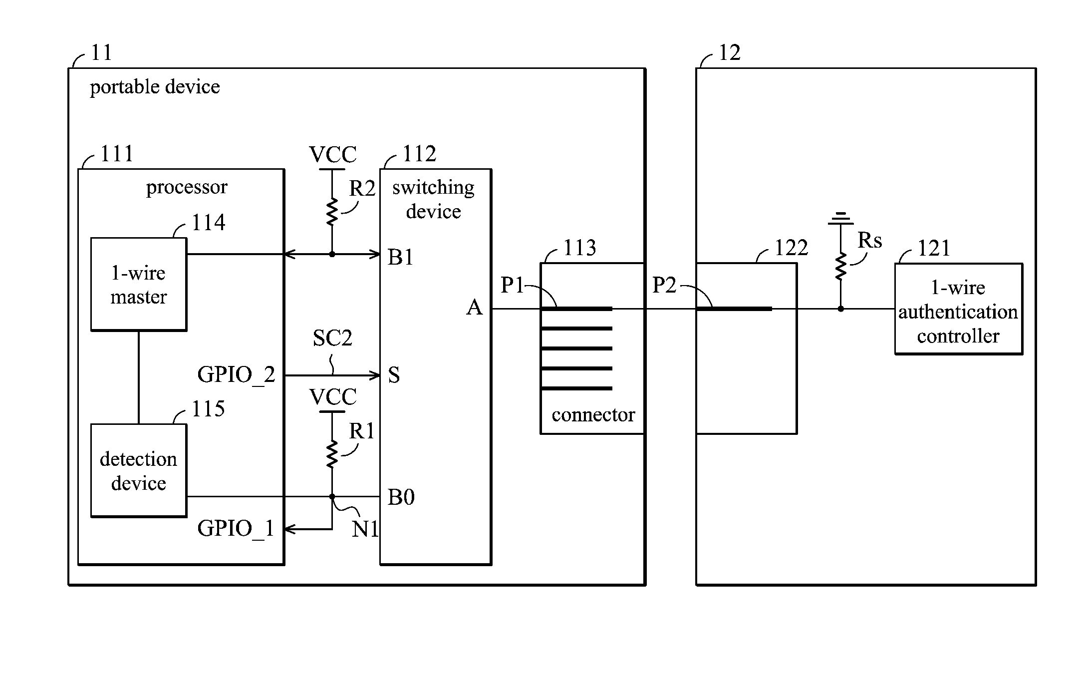
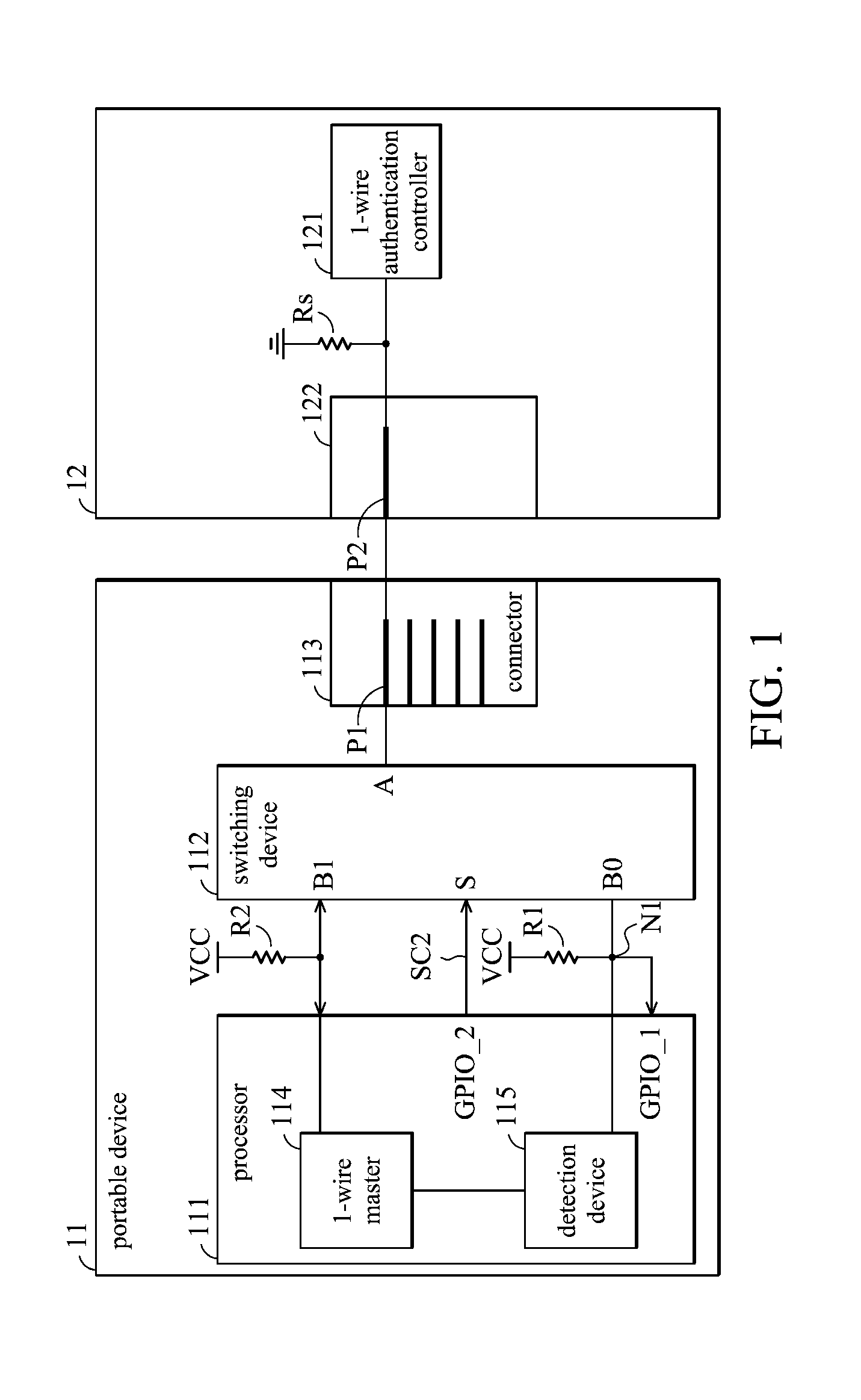
[0017]FIG. 1 is a schematic diagram of an embodiment of a portable device according to the invention. The portable device 11 comprises a housing, wherein the processor 111 and the switching device 112 are embedded inside of the housing, and a connector 113 is embedded in the housing for connection to external devices. The portable device 11 connects to a connector 122 of the peripheral device 12 via the connector 113. In this embodiment, the connector 113 is a micro USB connector. The micro USB connector comprises 5 pins, wherein an identification pin (the pin P1 in FIG. 1) is used only for the USB On-The-Go standard, and does not work at normal situation. Thus, the pi...


PUM


Abstract

An electronic device includes a housing, a connector port and a switching device. The connector port receives a peripheral device. The processor is electrically connected to the connector port and includes a detection pin and a 1-wire pin. The switching device is coupled between the connector port and the processor to selectively connect the connector port to one of the detection pin or the 1-wire pin. When the peripheral device is inserted into the connector port, the processor controls the switching device to connect the connector port to the detection pin to determine whether the connected peripheral device is a 1-wire device. When the processor determines that the connected peripheral device is a 1-wire device, the processor controls the switching device to connect the connector port to the 1-wire pin and the processor executes 1-wire communication with the peripheral device via the 1-wire pin.

Description

BACKGROUND OF THE INVENTION[0001]1. Field of the Invention[0002]The invention relates to a communication method between an electronic device and a peripheral device, and more particularly to a communication method between an electronic device and a 1-wire peripheral device.[0003]2. Description of the Related Art[0004]Portable devices, such as smart phones, tablets or personal digital assistants, have become necessities in business or for personal usage. To increase the functionality of portable devices, lots of peripheral devices have been developed for the portable devices. Furthermore, to decrease the number of types of connectors of the portable devices and the complexity of the bus, a 1-wire bus has therefore been adopted. The 1-wire bus is a simple bus having only one transmission line, where control and communication can be implemented. The number of Input / output ports can be saved and the system design of portable devices can be made simpler, thus, reducing hardware costs for...

Claims


Application Information

Patent Timeline
Patent Type & Authority Applications(United States)
IPC IPC(8): G06F1/16
CPCG06F13/4081G06F13/4022G06F1/1632Y02D10/00
Inventor HUNG, CHING-CHUNGLAI, YU-PENGCHANG, WEI-CHIH
Owner HTC CORP
Why Eureka
Try Eureka