
Method for Manufacturing Liquid Crystal Display Device and Liquid Crystal Display Device

Active Publication Date: 2013-12-05
TCL CHINA STAR OPTOELECTRONICS TECH CO LTD
View PDF3 Cites 2 Cited by
  • Summary
  • Abstract
  • Description
  • Claims
  • Application Information

AI Technical Summary

Benefits of technology

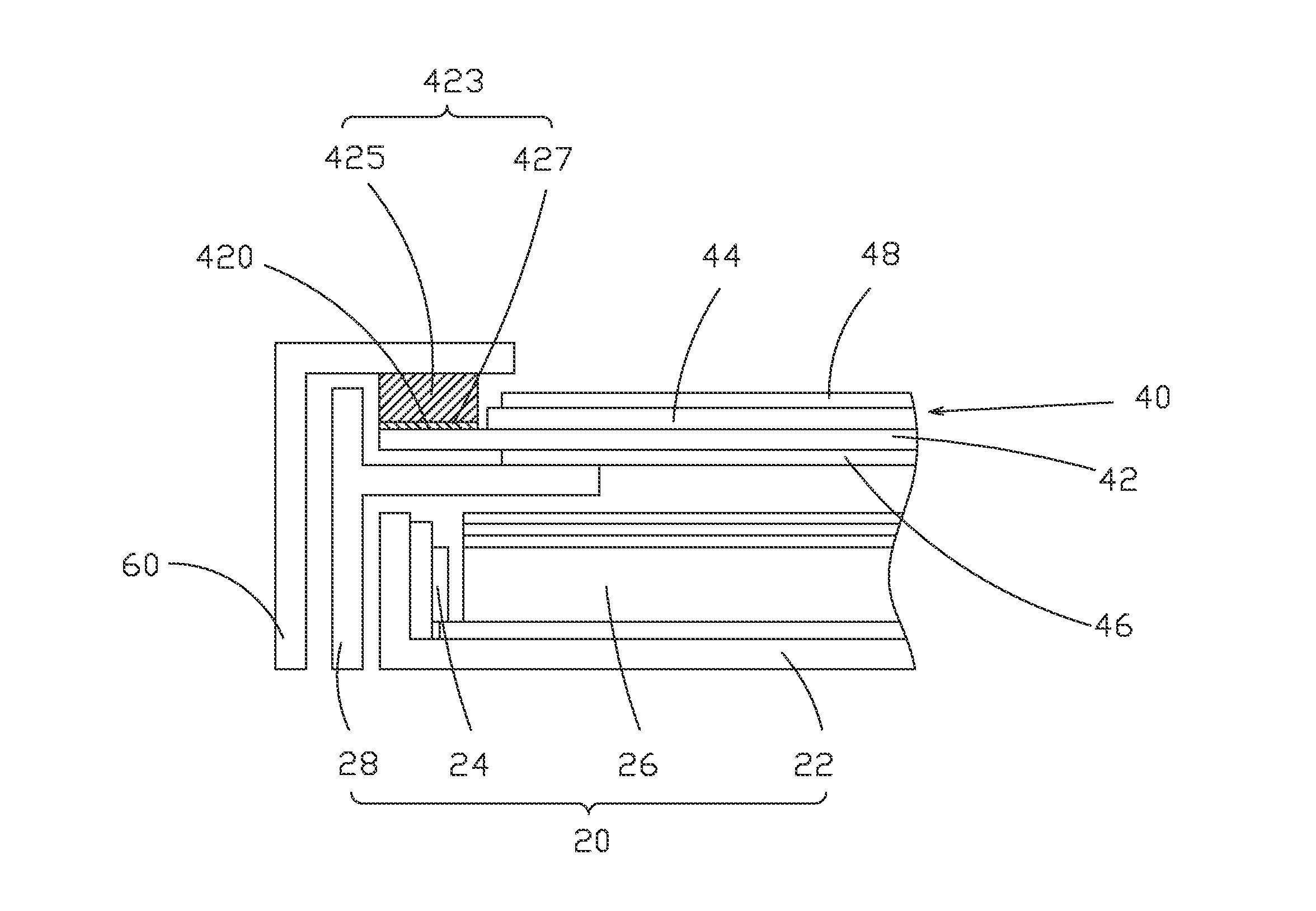
The present invention is a method and device for manufacturing a liquid crystal display. The invention uses cushioning tapes to prevent the display panel from separating from the front bezel during operation. The cushioning tapes have adhesive bodies that shift off the sites of flip chip films, preventing abnormal bright line defects that might occur during re-working of the flip chip films. The invention is easy to operate and cost-effective.

Problems solved by technology

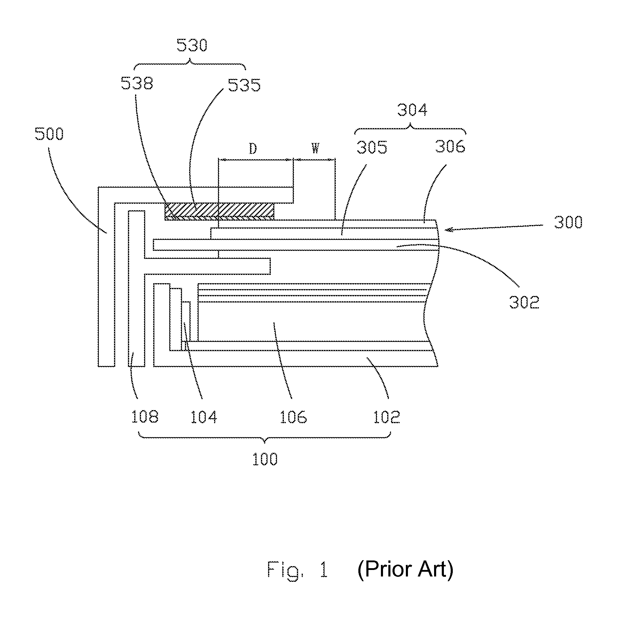
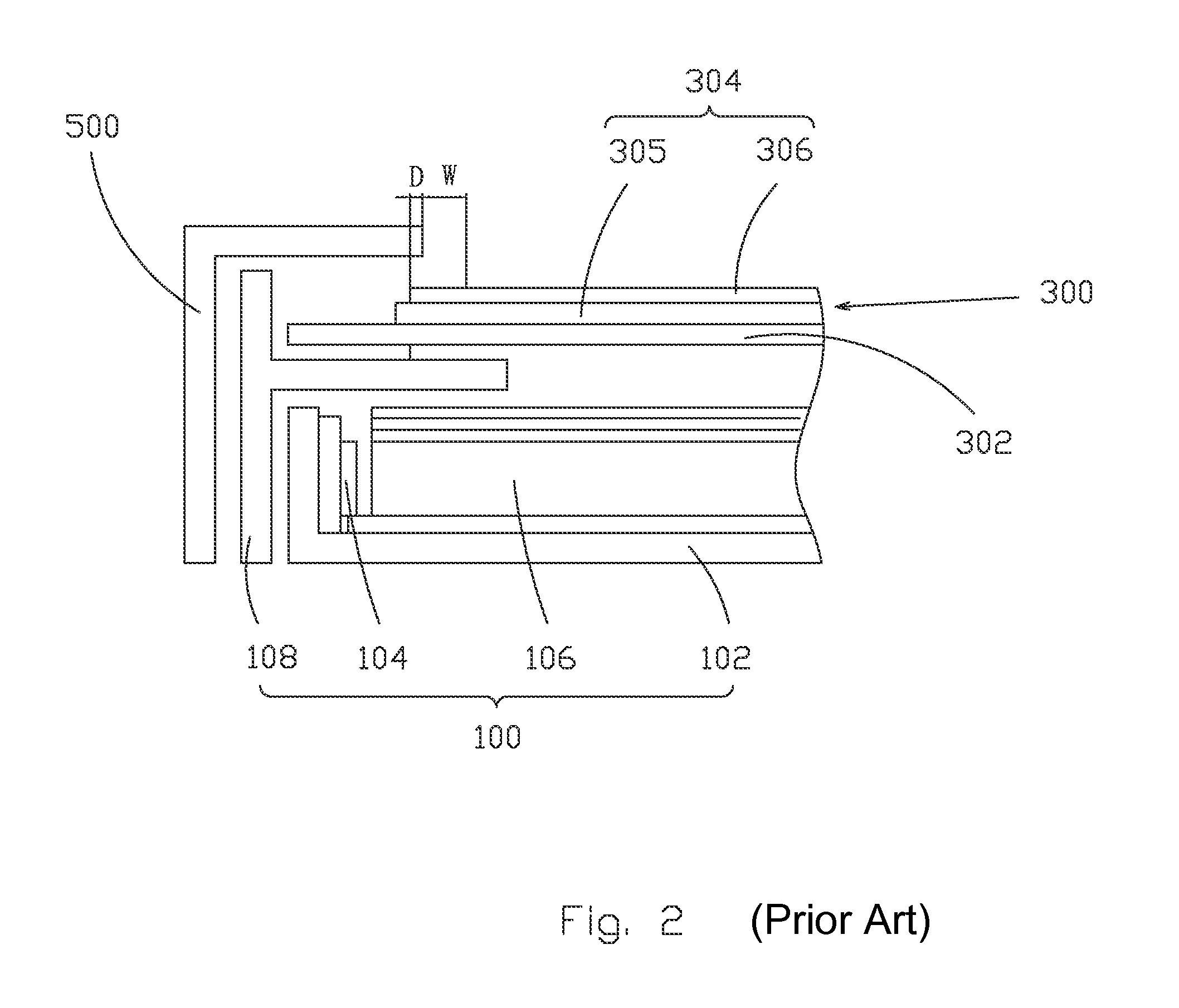
Under this condition, it is no longer able to attach the cushioning tape 530, and as a consequence, it is not able to prevent the liquid crystal display panel 300 from separating from the front bezel 500.
This makes peeling off the cushioning tapes 530 may also cause the flip chip films 700 to be simultaneously peeled off, resulting in bright line defects occurring in a liquid crystal display device.

Method used


Image

  • Method for Manufacturing Liquid Crystal Display Device and Liquid Crystal Display Device
  • Method for Manufacturing Liquid Crystal Display Device and Liquid Crystal Display Device
  • Method for Manufacturing Liquid Crystal Display Device and Liquid Crystal Display Device

Examples


Embodiment Construction

[0036]To further expound the technical solution adopted in the present invention and the advantages thereof, a detailed description is given to a preferred embodiment of the present invention and the attached drawings.

[0037]Referring to FIG. 5, with simultaneous reference to FIGS. 6 and 7, the present invention provides a method for manufacturing a liquid crystal display device, which comprises the following steps:

[0038]Step 1: providing a backlight module 20, a liquid crystal display panel 40, and a front bezel 60. The liquid crystal display panel 40 comprises a TFT substrate 42, a CF substrate 44 attached to the TFT substrate 42, and liquid crystal (not shown) interposed between the TFT substrate 42 and the CF substrate 44. An interval zone 420 is formed between an edge of the TFT substrate 42 and an edge of the CF substrate 44. A plurality of flip chip films 421 is mounted at intervals to the interval zone 420. The flip chip films 421 functions to electrically connect the liquid ...


PUM


Abstract

The present invention provides a method for manufacturing a liquid crystal display device, which includes (1) providing a backlight module, a liquid crystal display panel, and a front bezel, wherein the liquid crystal display panel includes a TFT substrate, a CF substrate attached to the TFT substrate, and liquid crystal interposed between the substrates, an interval zone being formed between an edge of the TFT substrate and an edge of the CF substrate, flip chip films being mounted at intervals to the interval zone; (2) attaching cushioning tapes to the interval zone of the TFT substrate at locations other than the flip chip films; (3) assembling the liquid crystal display panel to the backlight module; and (4) assembling the front bezel to the liquid crystal display panel in such a way that the front bezel is positioned on the cushioning tapes of the liquid crystal display panel.

Description

BACKGROUND OF THE INVENTION[0001]1. Field of the Invention[0002]The present invention relates to the field of liquid crystal displaying, and in particular to a method for manufacturing a liquid crystal display device and a liquid crystal display device.[0003]2. The Related Arts[0004]Liquid crystal display (LCD) has a variety of advantages, such as thin device body, low power consumption, and being free of radiation, and is thus widely used. Most of the LCDs that are currently available in the market are backlighting LCDs, which comprise a liquid crystal display panel and a backlight module. The working principle of the liquid crystal display panel is that liquid crystal molecules are interposed between two parallel glass substrates and a plurality of vertical and horizontal fine electrical wires is arranged between the two glass substrates, whereby the liquid crystal molecules are controlled to change direction by application of electricity in order to refract light emitting from th...

Claims


Application Information

Patent Timeline
IPC IPC(8): G02F1/136H01J9/00G02F1/13357
CPCG02F1/1333G02F1/13454G02F2201/50G02F2201/54G02F1/13332
Inventor TANG, GUOFUCHEN, SHIHHSIANG
Owner TCL CHINA STAR OPTOELECTRONICS TECH CO LTD
Learn More