
Dry-type transformer and method of manufacturing a dry-type transformer

a technology of transformers and transformers, which is applied in the field of dry-type transformers and the method of manufacturing a dry-type transformer, can solve the problems of cumbersome and difficult air ducting into the windings, and achieve the effect of reducing the number of transformers

Active Publication Date: 2013-12-05
HITACHI ENERGY SWITZERLAND AG
View PDF5 Cites 4 Cited by
  • Summary
  • Abstract
  • Description
  • Claims
  • Application Information

AI Technical Summary

Benefits of technology

The present invention relates to a dry-type electrical transformer coil assembly with improved cooling capabilities. The coil assembly includes at least one winding with an electrical conductor wound into concentric turns. A cooling sector is formed between adjacent turns with a plurality of spacers positioned inside the cooling sector to create air ducts between them. An electrical shield is placed within the cooling sector to shield the air ducts from electrical arcs. This design improves the cooling efficiency of the transformer and helps to prevent overheating, which can lead to damage and reduced performance. The method of manufacturing the transformer includes winding the electrical conductor and positioning the spacers to create the cooling sector and air ducts. The electrical shield is then added to protect the air ducts. The technical effect of this invention is to enhance the safety and reliability of the transformer by improving its cooling efficiency.

Problems solved by technology

The embodiment of cooling sectors or air ducts into the windings is to some extent rather difficult and cumbersome, especially when turns are wound in a disc-type configuration.

Method used


Image

  • Dry-type transformer and method of manufacturing a dry-type transformer
  • Dry-type transformer and method of manufacturing a dry-type transformer
  • Dry-type transformer and method of manufacturing a dry-type transformer

Examples


Embodiment Construction

[0020]Exemplary embodiments of the present disclosure provide a dry-type electrical transformer and a method of manufacturing a dry-type electrical transformer having improvements over known techniques.

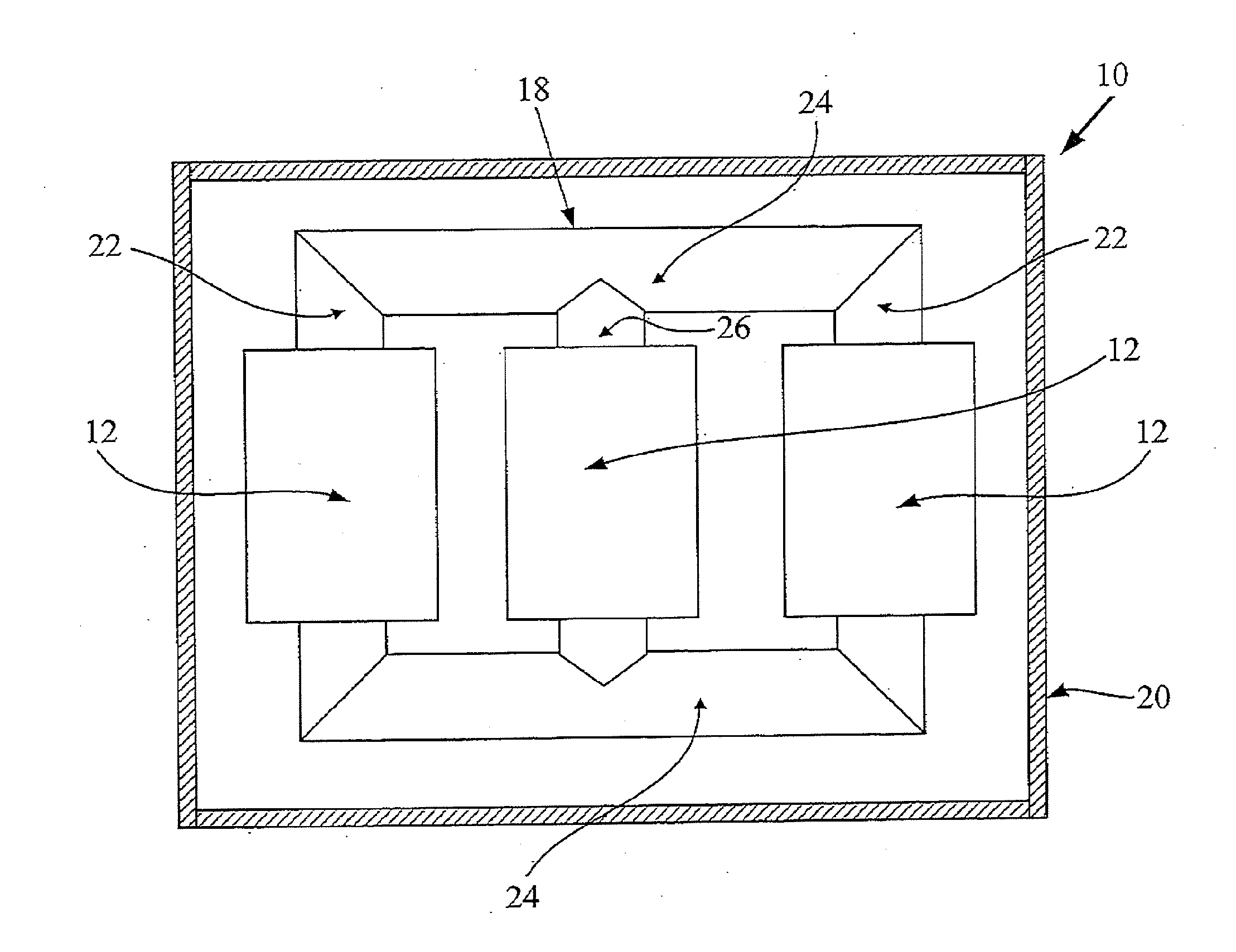
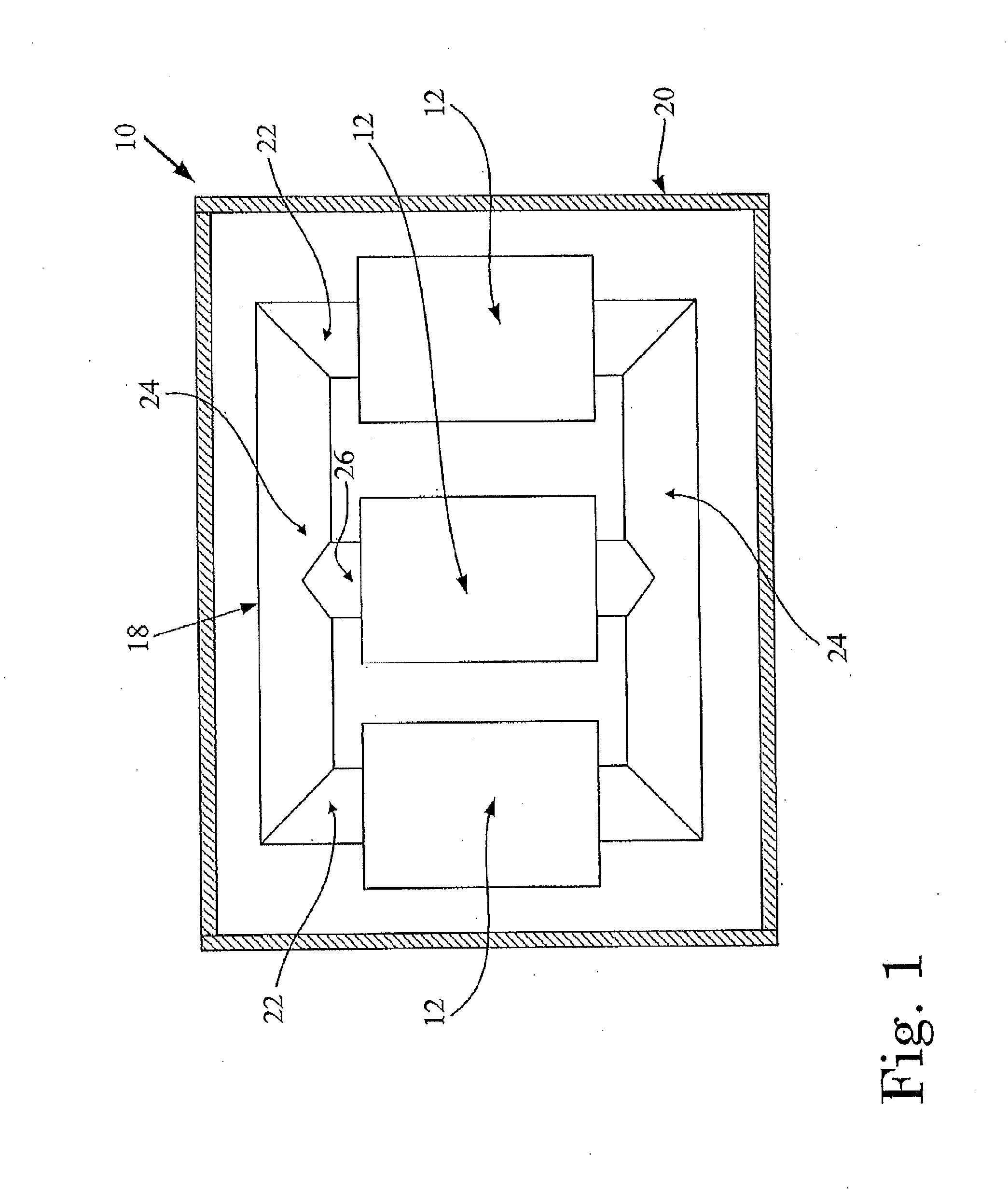
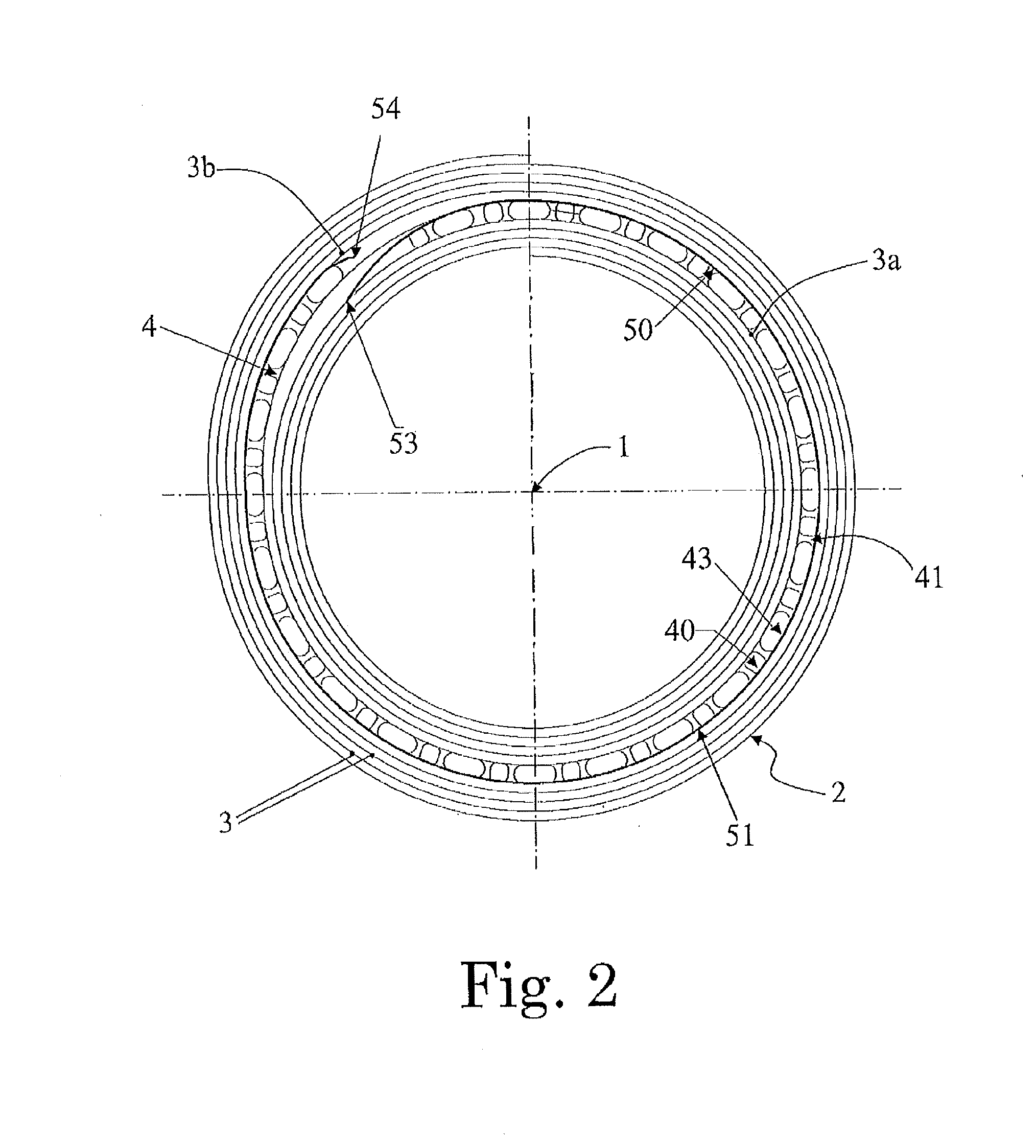
[0021]Accordingly, an exemplary embodiment of the present disclosure provides a dry-type electrical transformer including a coil assembly having at least one winding, where the at least one winding includes an electrical conductor wound around a longitudinal axis into a plurality of concentric turns. The transformer also includes at least one cooling sector defined between adjacent turns of the plurality of concentric turns, and a plurality of spacers which are positioned inside the at least one cooling sector and are spaced from each other so as to allow having a plurality of air ducts each defined between two adjacent spacers of the plurality of spacers. At least one electrical shield is positioned in the at least one cooling sector and is arranged so as to electrically shield the p...


PUM

PropertyMeasurementUnit
electrical conductoraaaaaaaaaa
electricalaaaaaaaaaa
electric energyaaaaaaaaaa

Abstract

A dry-type electrical transformer includes a coil assembly having at least one winding wound into a plurality of concentric turns, at least one cooling sector defined between adjacent concentric turns, spacers positioned inside the cooling sector and spaced from each other to allow a plurality of air ducts each defined between two adjacent spacers, and at least one electrical shield positioned in the cooling sector and arranged to electrically shield the air ducts. At least one electrical shield is positioned in the cooling sector and arranged to electrically shield the air ducts. The electrical shield include a first end edge connected to the turn at the inner side of the cooling sector, a second end edge which is free and electrically insulated from the surrounding parts, and a central portion extending between the first and second end edges and is positioned at the outer side of the spacers.

Description

RELATED APPLICATIONS[0001]This application claims priority as a continuation application under 35 U.S.C. §120 to PCT / EP2012 / 051417, which was filed as an International Application on Jan. 30, 2012 designating the U.S., and which claims priority to European Application 11153738.7 filed in Europe on Feb. 8, 2011. The entire contents of these applications are hereby incorporated by reference in their entireties.FIELD[0002]The present disclosure relates to an electrical transformer. More particularly, the present disclosure relates to a dry-type electrical transformer having an improved coil assembly, and to a method of manufacturing a dry-type electrical transformer.BACKGROUND INFORMATION[0003]The basic task of electrical transformers is to allow for the exchange of electric energy between two or more electrical systems of usually different voltages. In practice, a transformer converts electricity at one voltage to electricity at another voltage, either of higher or lower value.[0004]M...

Claims


Application Information

Patent Timeline
Patent Type & Authority Applications(United States)
IPC IPC(8): H01F27/00H01F41/06
CPCH01F27/008H01F41/06H01F27/288H01F27/322H01F41/063H01F2027/328Y10T29/49071H01F27/36H01F27/363H01F27/28H01F27/32
Inventor ROY, CARLOSMURILLO, RAFAELCEBRIAN LLES, LORENA
Owner HITACHI ENERGY SWITZERLAND AG
Learn More