Adaptive equalizer, acoustic echo canceller device, and active noise control device
a technology of acoustic echo canceller and adaptive equalizer, which is applied in the direction of active noise control, sound producing devices, instruments, etc., can solve the problems of long time to convergence of identification errors, increase in the number of updates of filter coefficients required to converge identification errors, and inability to rapidly reduce identification errors or to a sufficient level. , to achieve the effect of rapid reduction of identification errors
- Summary
- Abstract
- Description
- Claims
- Application Information
AI Technical Summary
Benefits of technology
Problems solved by technology
Method used
Image

Examples
embodiment 1
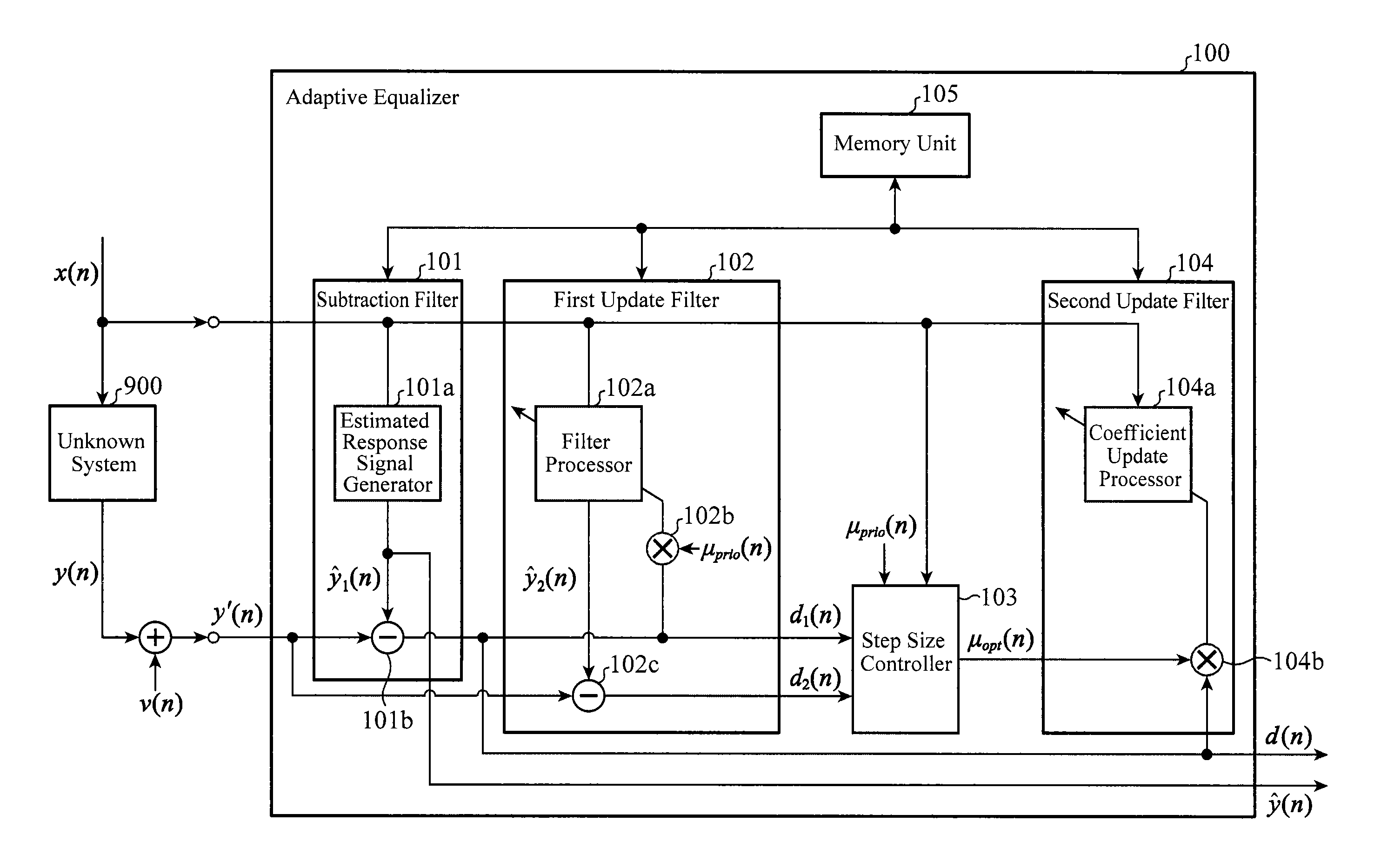
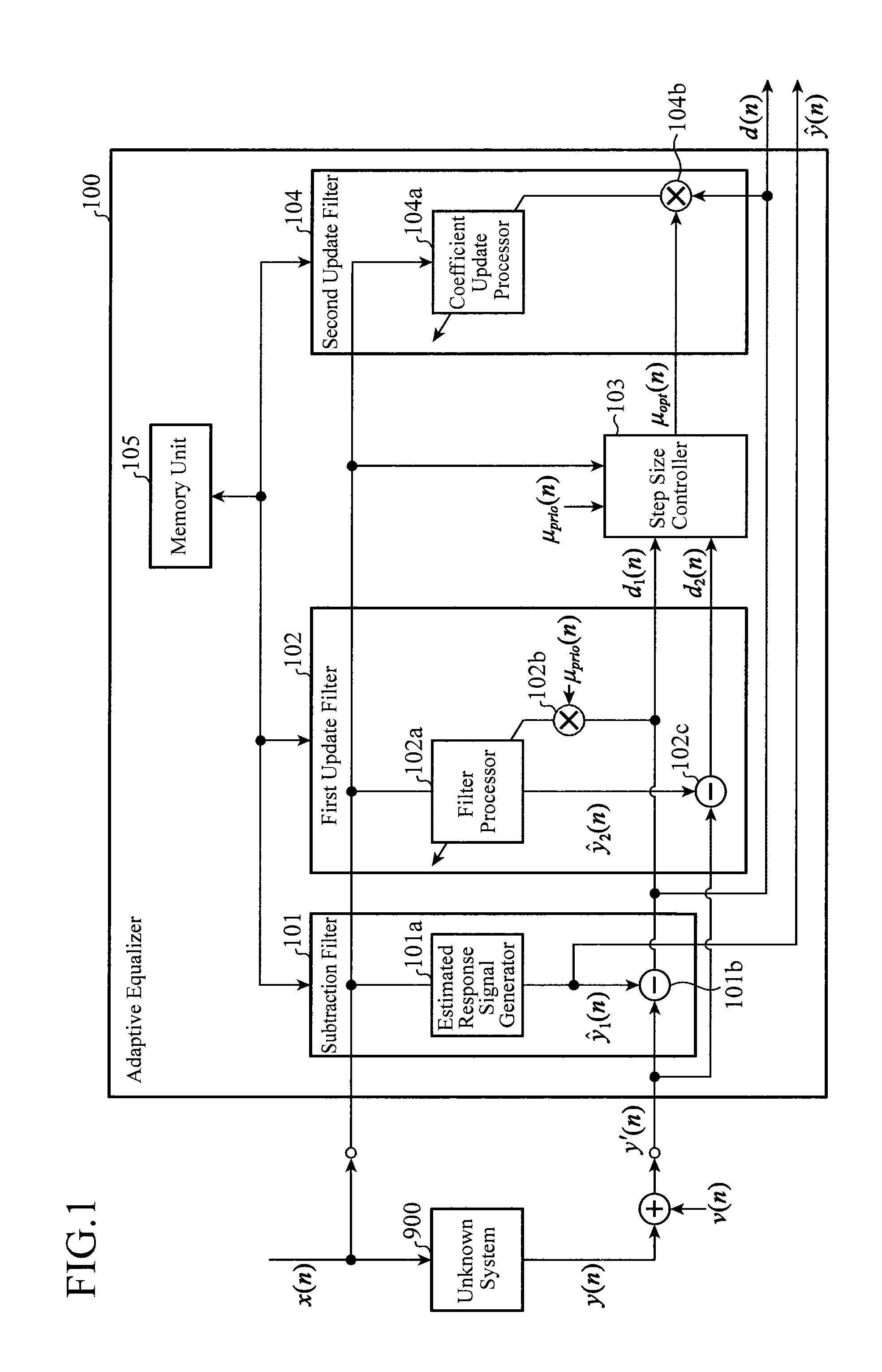
[0039]FIG. 1 is a block diagram showing a configuration of an adaptive equalizer according to Embodiment 1 of the present invention. In FIG. 1, an adaptive equalizer 100 is composed of: a subtraction filter 101 that generates a first estimated response signal and a first residual signal; a first update filter 102 that performs a coefficient update on a filter coefficient sequence and generates a second estimated response signal using the updated filter coefficient sequence; a step size controller 103 that determines a variable update step size; a second update filter 104 that performs a coefficient update on the filter coefficient sequence; and a memory unit 105 that stores the filter coefficient sequence. The subtraction filter 101 includes an estimated response signal generator 101a and a subtractor 101b. The first update filter 102 includes a filter processor 102a, a multiplier 102b, and a subtractor 102c. The second update filter 104 includes a coefficient update processor 104a ...
embodiment 2
[0114]In the above-described Embodiment 1, the configuration is shown in which after a variable update step size μopt(n) is calculated, the calculated variable update step size μopt(n) is applied to a second update filter 104 to perform a coefficient update on a filter coefficient sequence. However, when a change in disturbance condition or in the transfer function of an unknown system 900 is relatively small, there may be a case in which there is no great difference in value between a variable update step size μopt(n−1) calculated last time and the latest variable update step size μopt(n). For example, when a disturbance is white noise or pink noise that has constant statistical properties or a random signal similar thereto, it can be assumed that a change in disturbance is sufficiently small with respect to the frequency of updates to coefficients. Thus, it is expected that there is almost no change in the value of a variable update step size to be calculated between the last one ...
embodiment 3
[0124]In the above-described Embodiment 1, the configuration is shown in which in a first update filter 102, after performing a coefficient update on a prior update filter coefficient sequence using an input signal x(n) and an observed response signal y′(n), a second residual signal d2(n) is immediately obtained using the same input signal x(n) and the same observed response signal y′(n), and the second residual signal d2(n) is used for calculation of a variable update step size μopt(n).
[0125]However, an apparent correlation may temporarily strongly appear between an input signal x(n) with a limited length and a disturbance signal v(n). By this, there may be a case of outputting a second estimated response signal ŷ2 (n) in which a prior update filter coefficient sequence ĥprio(n) removes a part of the disturbance signal v(n) contained in a provided observed response signal y′(n). In this case, an apparent variance σd22(n) of a second residual signal d2(n) may temporarily become smal...
PUM
 Abstract
Description
Claims
Application Information
 - R&D
- Intellectual Property
- Life Sciences
- Materials
- Tech Scout
- Unparalleled Data Quality
- Higher Quality Content
- 60% Fewer Hallucinations
Browse by: Latest US Patents, China's latest patents, Technical Efficacy Thesaurus, Application Domain, Technology Topic, Popular Technical Reports.
© 2025 PatSnap. All rights reserved.Legal|Privacy policy|Modern Slavery Act Transparency Statement|Sitemap|About US| Contact US: help@patsnap.com