
Protective Sheath

a protective sheath and shielding technology, applied in the field of protective sheaths, can solve the problems of inconvenient carrying of spare batteries and external batteries with portable electronic devices, inconvenient supply of electric power to portable electronic devices, and inability to carry them together with portable electronic devices

Inactive Publication Date: 2013-11-21
HSU FU YI
View PDF6 Cites 3 Cited by
  • Summary
  • Abstract
  • Description
  • Claims
  • Application Information

AI Technical Summary

Benefits of technology

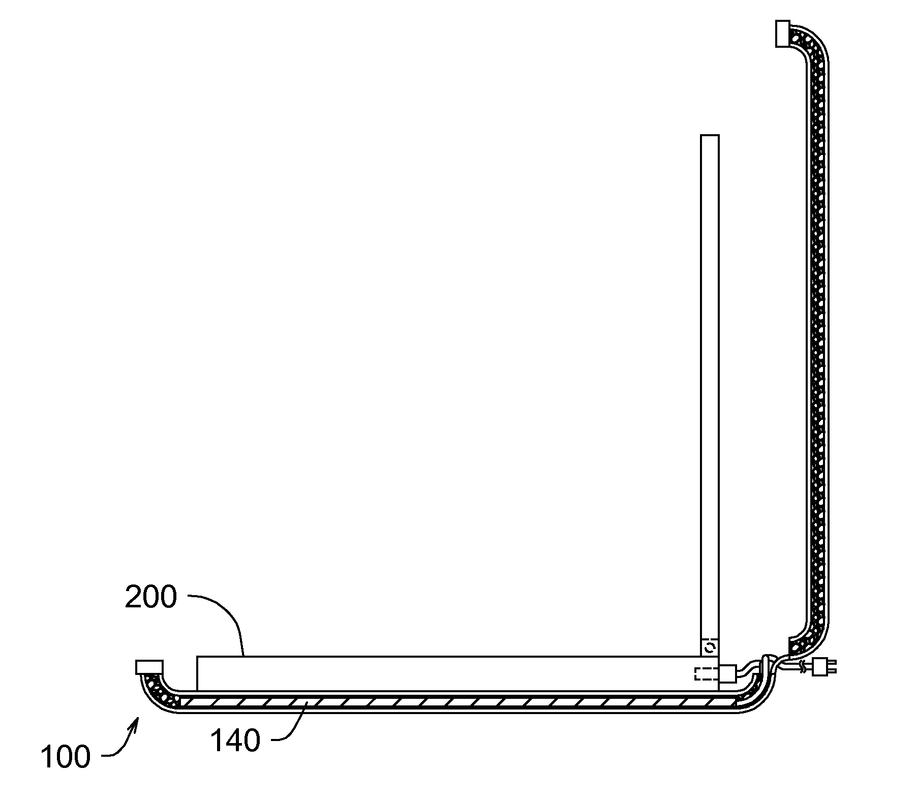
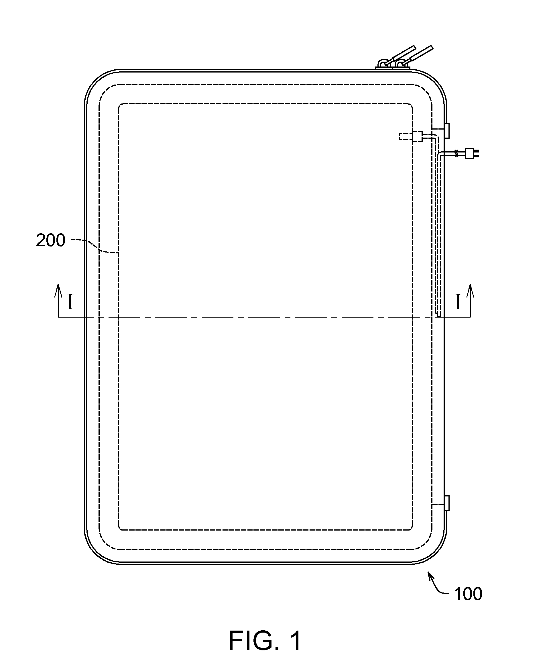
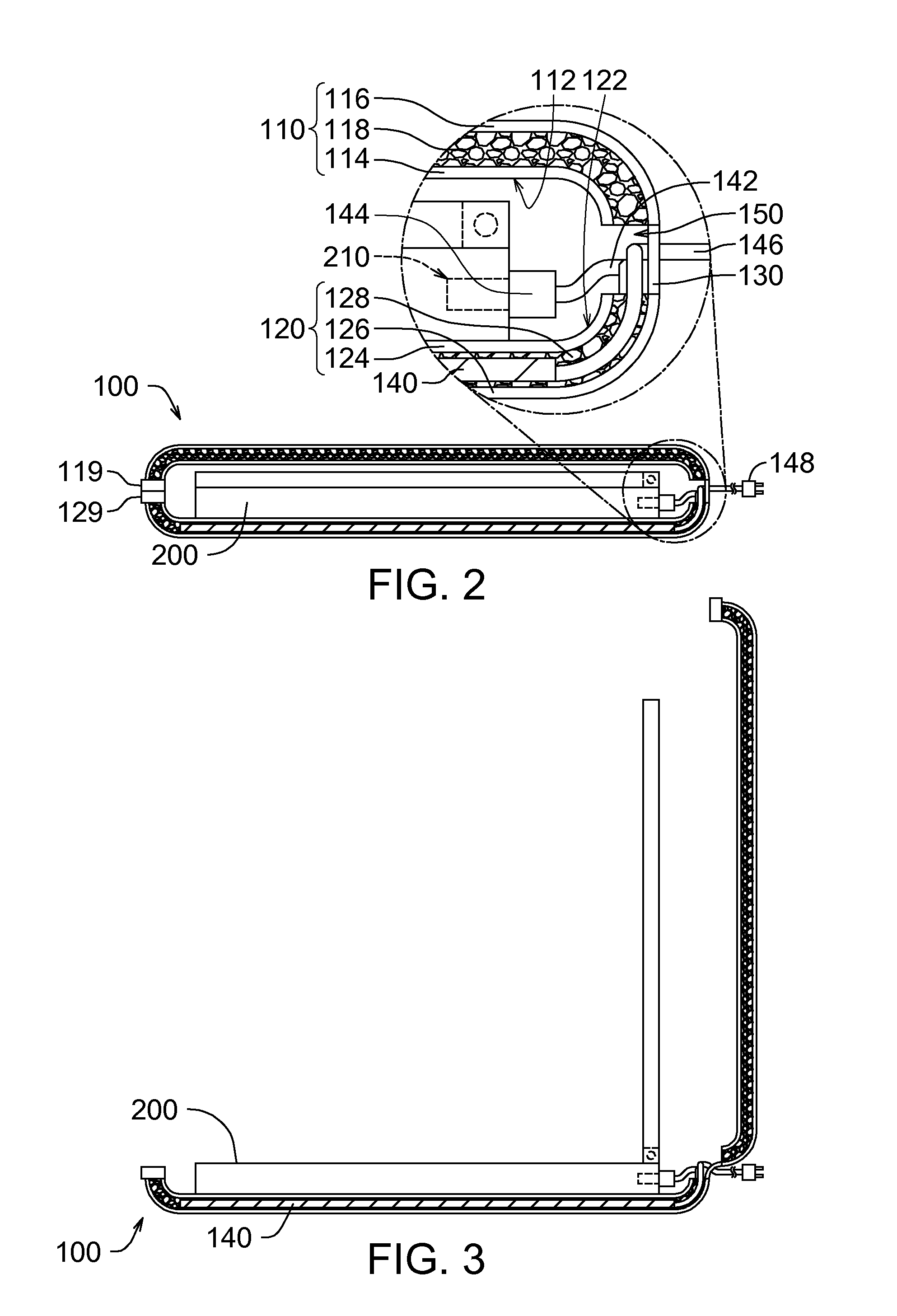
The present invention provides a protective sheath with a battery module embedded within it. This allows the sheath to not only protect the electronic device, but also to provide electric power to it anytime and anywhere. The sheath can also supply power to the device without taking it out of the sheath. Additionally, the battery module can also connect with an external power source to charge it. The technical effect of this invention is to provide a convenient and efficient way to power portable electronic devices.

Problems solved by technology

It should be noted that the commercially available protective sheathes are usually designed for merely receiving the portable electronic device without any individual space for receiving the peripheral devices thereof, such as a spare battery, an external battery, a power supply and so on, and thus both the spare battery and the external battery are inconvenient to be carried together with the portable electronic device.
In such a case, if the spare battery or the external battery is forced to be received in the protective sheath together with the portable electronic device, the case of the portable electronic device is likely to be damaged.
Further, although some of the commercially available protective bags are designed with an individual space for receiving a spare battery or an external battery, it is inconvenient to supply electric power to the portable electronic device by using the spare battery (or the external battery) as well since both of the portable electronic device and the spare battery (or the external battery) should be took out of the protective bags before being assembled together.

Method used


Image

  • Protective Sheath
  • Protective Sheath
  • Protective Sheath

Examples


Embodiment Construction

[0019]Reference will now be made in detail to specific embodiments of the present invention. Examples of these embodiments are illustrated in the accompanying drawings. While the invention will be described in conjunction with these specific embodiments, it will be understood that it is not intended to limit the invention to these embodiments. In fact, it is intended to cover alternatives, modifications, and equivalents as may be included within the spirit and scope of the invention as defined by the appended claims. In the following description, numerous specific details are set forth in order to provide a thorough understanding of the present invention. The present invention may be practiced without some or all of these specific details. In other instances, well-known process operations are not described in detail in order not to obscure the present invention.

[0020]FIG. 1 illustrates a structural schematic top view of a protective sheath according to an embodiment of the present i...


PUM

PropertyMeasurementUnit
electric poweraaaaaaaaaa
polaritiesaaaaaaaaaa
flexibleaaaaaaaaaa

Abstract

A protective sheath for a portable electronic device comprising two cover plates, a connection piece and a battery module is provided. The two cover plates respectively have an inner surface. In addition, the two cover plates connect to each other via the connection piece and are capable of being folded relative to each other via the connection piece, so as to enable the two inner surfaces to cover two opposite sides of the portable electronic device respectively. The battery module is disposed to at least one of the two cover plates and has a first connection cable, wherein the first connection cable can be electrically connected with the portable electronic device, so as to enable the battery module to supply electric power to the portable electronic device.

Description

CROSS-REFERENCE TO RELATED APPLICATIONS[0001]This application claims priority from Taiwan Patent Application No. 101209343, filed May 17, 2012, the contents of which are hereby incorporated by reference in their entirety for all purposes.FIELD OF THE INVENTION[0002]The present invention generally relates to a protective sheath, and more particularly to a protective sheath for a portable electronic device.DESCRIPTION OF THE RELATED ART[0003]With the development of technology, various portable electronic devices, such as a multimedia player (MP3, MP4 and so on), a cell phone, a personal digital assistant (PDA), a hand-held game console, an electronic book (E-book), a tablet personal computer (tablet PC), a netbook, a notebook and so on, have become an integral part of modern life to many people. To compare with the traditional desktop personal computer (desktop PC), a main advantage of the portable electronic device is easy to get carried. Therefore, in recent years, we can see people...

Claims


Application Information

Patent Timeline
Patent Type & Authority Applications(United States)
IPC IPC(8): H01M2/02
CPCH01M2/0202A45C11/00A45C15/00A45C2011/003G06F2200/1633Y02E60/10
Inventor HSU, FU-YI
Owner HSU FU YI
Learn More