
Bicycle light

a technology of bicycle lights and front lights, applied in cycle equipment, lighting and heating apparatus, light support devices, etc., can solve the problems of compact and efficient front lights that do not provide spot and flood beams, and the difficulty of creating a curved face that is optically clean

Active Publication Date: 2013-11-14
LIGHT & MOTION INDS
View PDF7 Cites 19 Cited by
  • Summary
  • Abstract
  • Description
  • Claims
  • Application Information

AI Technical Summary

Benefits of technology

This patent describes a new bicycle headlamp featuring amber side lights that can be activated or deactivated independently of the main lights. The front light includes a separate switch for the side lights, which can be turned off when not needed or turned on while the main lights are on. The side lights can also be set to a pulse mode or off. The technical effects of this patent include improved safety in traffic and more flexibility in controlling the headlamp's lighting.

Problems solved by technology

The challenges with that design was the difficulty in creating a curved face that is optically clean.
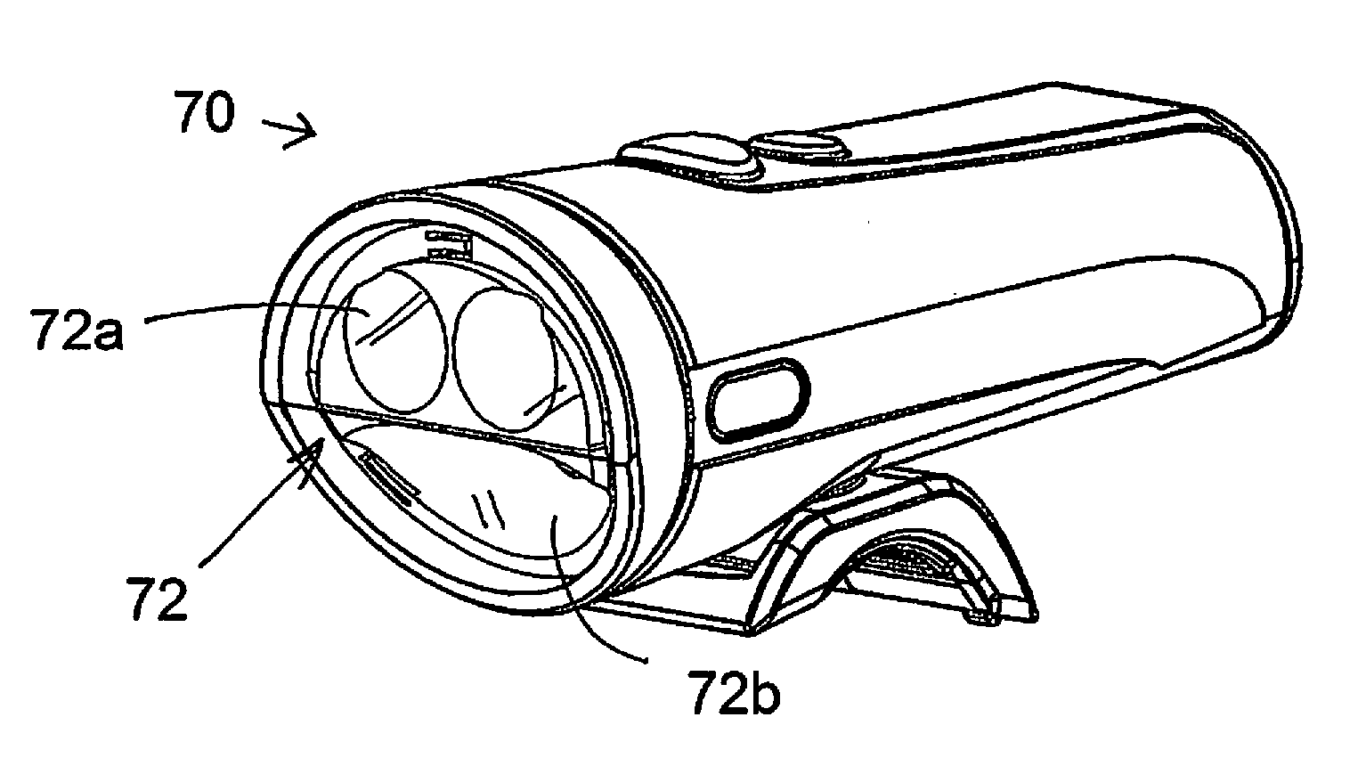
However, in available bicycle lights prior to this invention there has not been a compact and efficient front light providing spot and flood beams, with efficient optics and with optional side lights, as in the bicycle light described below.

Method used


Image

  • Bicycle light
  • Bicycle light
  • Bicycle light

Examples


Embodiment Construction

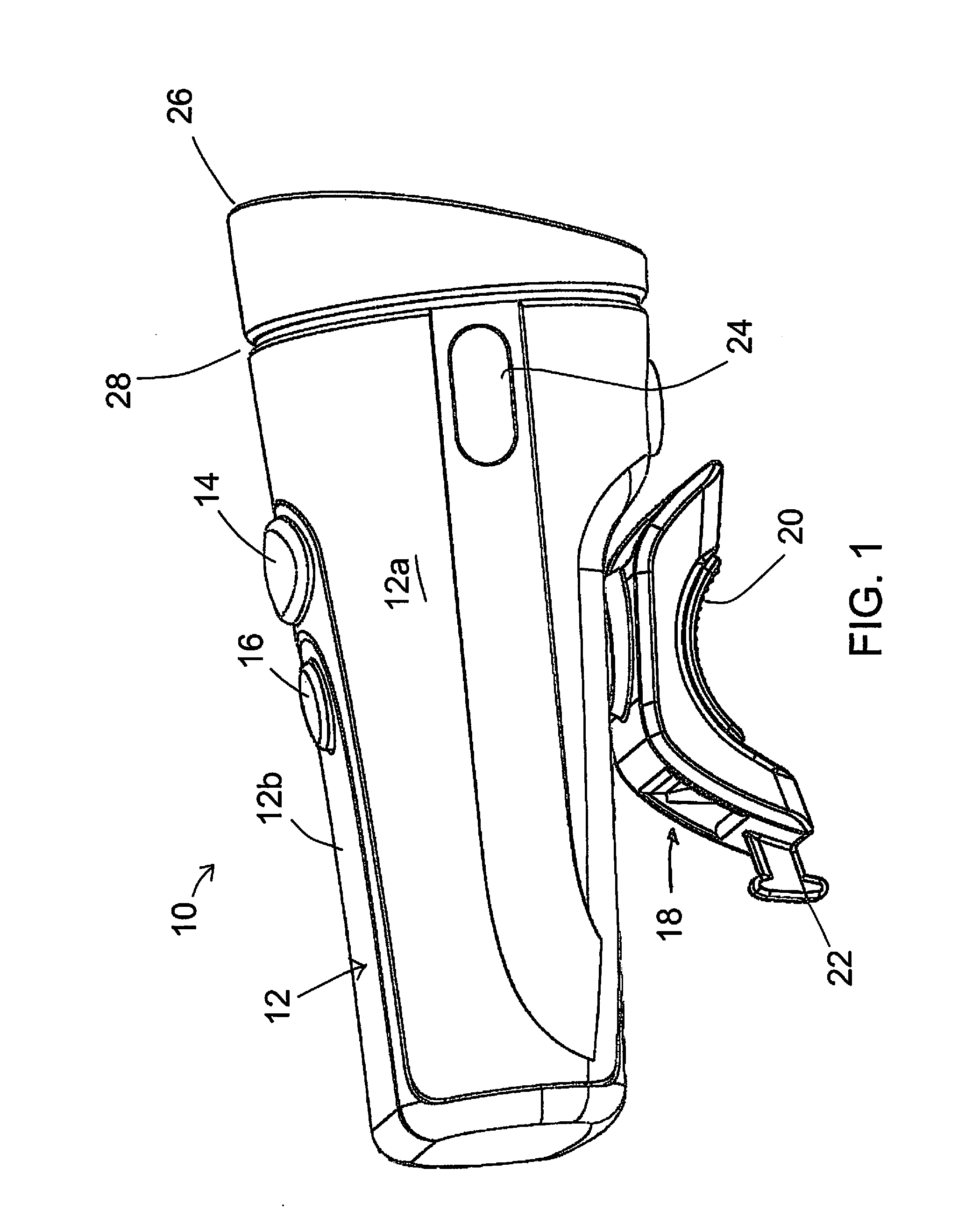
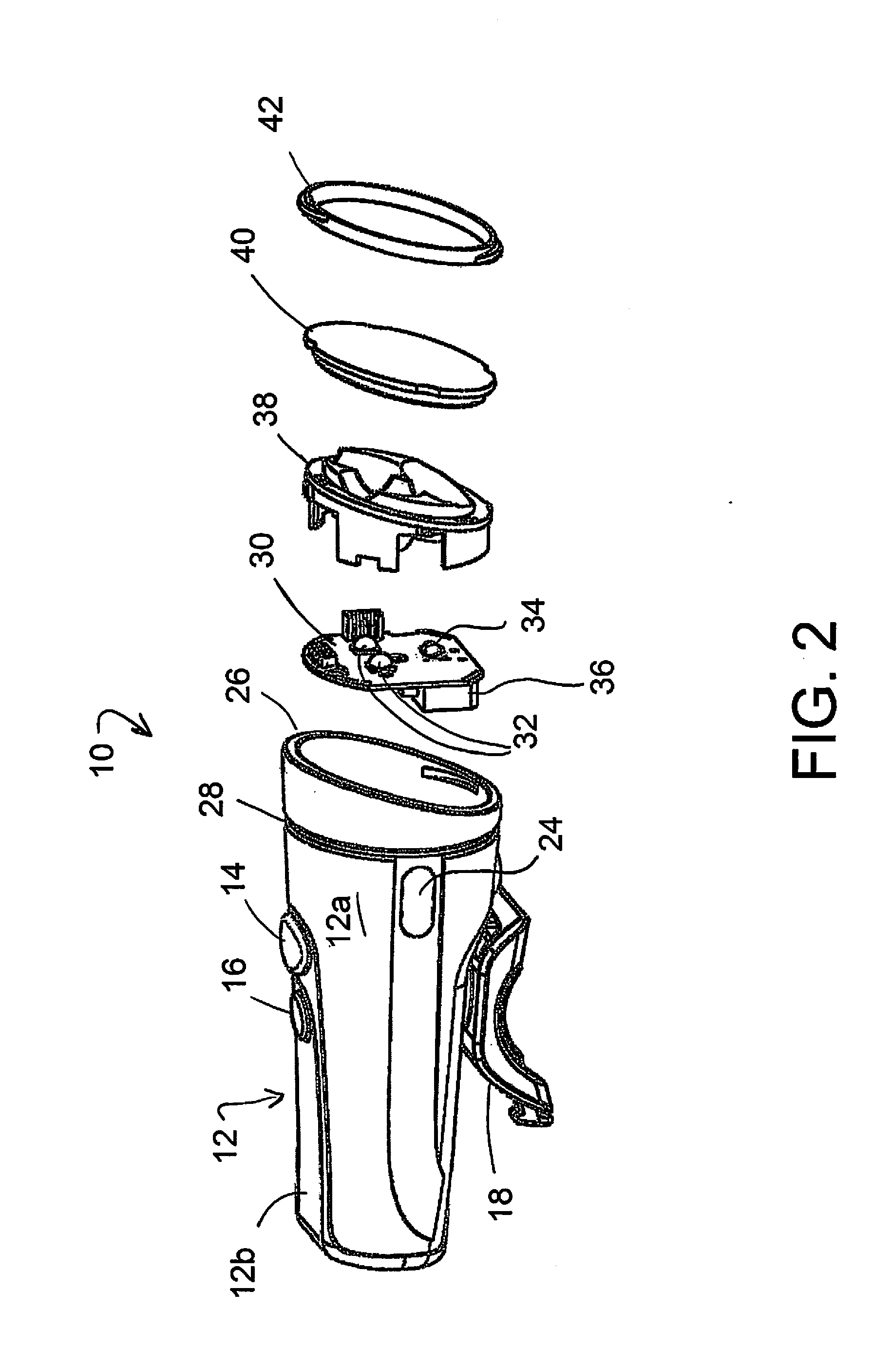
[0015]FIG. 1 shows a front bicycle light 10 of the invention, with a housing or casing 12 on which are mounted push button type switches 14 and 16, preferably at a top side as shown.

[0016]A connector bracket 18 is seen secured to the bottom side of the light casing 12. In a preferred form this connector has a handlebar-engaging surface 20, appropriately curved as shown, and a connection point 22 for a flexible, stretchable strap to be wrapped tightly around the bottom of the handlebar and secured back to the connector device 18. Other forms of connection to a bicycle can be used.

[0017]Left and right side lights 24 are included in a preferred embodiment of the front light of the invention. These project yellow or amber light, but other colors are also possible.

[0018]The front end 26 of the bicycle light is angled downwardly, as described above. The downward angle is relative to vertical or with respect to a plane indicated at 28 and defined by a decorative circumferential groove as s...


PUM


Abstract

A bicycle light for securing to a handlebar or other part of a bike, or to a rider's helmet, has an angled front face that allows use of a single, flat LED circuit board with one or more deep conic or parabolic reflectors positioned in front of the upper part of the board and one or more shallow reflectors in front of the bottom part of the board. This provides for both a spot beam produced by the deep reflector and flood light produced by the shallow reflector, in a compact and efficient assembly. Another important feature of the device is side lighting which can be independently controlled, important in affording the rider side lighting while in street traffic but the option to pulse or switch off the side lighting when riding on a trail.

Description

BACKGROUND OF THE INVENTION[0001]This invention concerns bicycle lights attachable to a bicycle (e.g. to handlebars) or to a rider's helmet. In particular the invention concerns a bicycle light of efficient and compact configuration, producing both spot and flood lighting and preferably with side lights.[0002]Front and rear bicycle lights have been available in many different forms. Front bike lights have been provided for attachment to handlebars and to helmets, have been self-contained with battery or wired to a separately mounted battery. The front lights typically have several modes of operation, i.e. steady or flashing, and sometimes have ability to adjust brightness. Some have switched on automatically with darkness. Side lights have been included on a few of them. Many models of front lights have been offered by Planet, Cygolite, Busch & Mueller, NightRider, Cat Eye, Knog, and Light & Motion.[0003]Some bicycle lights have provided light projection with fill light around a spo...

Claims


Application Information

Patent Timeline
Patent Type & Authority Applications(United States)
IPC IPC(8): B62J6/02F21V21/08
CPCB62J6/015B62J6/029B62J6/03B62J6/02
Inventor MCCASLIN, CHRISTOPHERWEISENFELD, GREGROBERTSON, BEAU JESSELO, ROXANNE
Owner LIGHT & MOTION INDS
Learn More