
Ice handling container

a technology for handling containers and containers, applied in the direction of containers preventing decay, packaging goods, lighting and heating apparatus, etc., can solve the problems of increasing the risk of container misuse, high risk of ice and/or container contamination, and unnecessary strain on users

Active Publication Date: 2013-10-31
ECOLAB USA INC
View PDF6 Cites 13 Cited by
  • Summary
  • Abstract
  • Description
  • Claims
  • Application Information

AI Technical Summary

Benefits of technology

The invention is an improved ice handling container with a bottom wall and sidewalls that can be hung with a hook. It also includes a handle assembly with a handle and hook that can be easily nested in a recess in the sidewaU. The technical effect of this design is that it prevents two or more containers frombeing nested together after use, which makes them easier to hang and handle. Additionally, the handle assembly can be easily removed from the container to save space and reduce costs.

Problems solved by technology

Handling ice using traditional and currently available containers, such as movement of ice from the point of production to a point of dispension and / or use (e.g., from the back of the house to the front of the house in restaurants) has limitations, including a high risk of the ice and / or container becoming contaminated.
Containers are also now configured to hold greater volumes of ice, but still suffer from ergonomical constraints that put unnecessary strain on the user and increase the risk of misuse of the container, which lends to contamination of the container and / or the ice.
The growing size of these containers also often prohibits use and subsequent sanitization within a standard size dishmachine.
The ever increasing size of these containers also increases the already burgeoning costs for shipping them from manufacturers and suppliers, and to purchasers.

Method used


Image

  • Ice handling container
  • Ice handling container
  • Ice handling container

Examples


Embodiment Construction

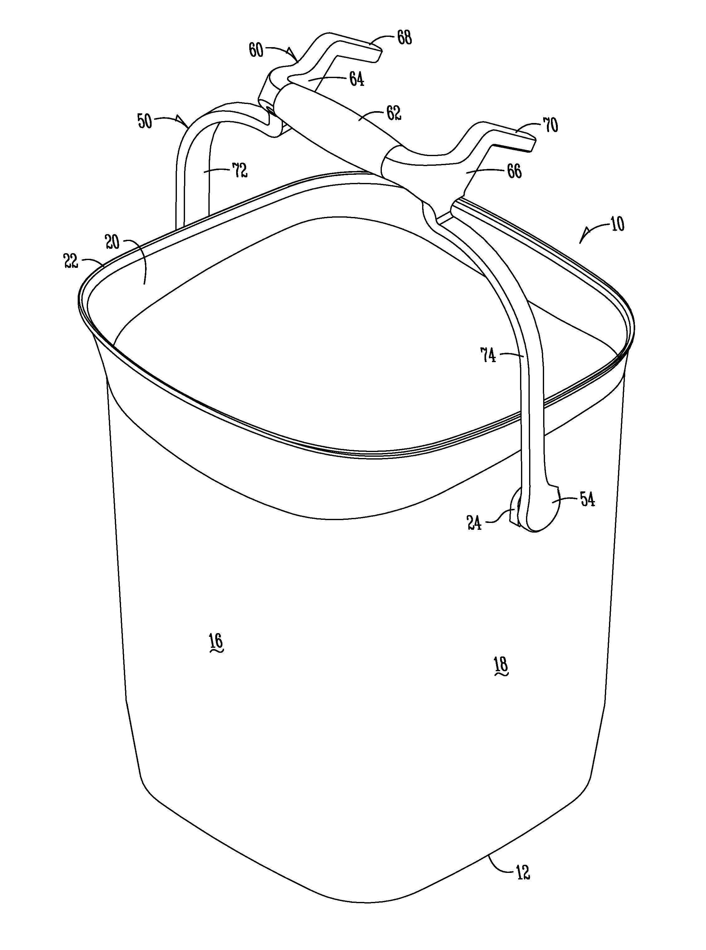
[0022]Referring to the figures, there is generally disclosed in FIGS. 1-9 an improved ice handling container for handling and transporting ice in a sanitary manner. Also disclosed are methods for using the improved ice handling container according to exemplary aspects of the present invention.

[0023]FIG. 1 is a perspective view of an ice handling container 10 according to an exemplary aspect of the present invention. The container 10 includes a base 12 with feet 14 best shown in FIG. 4 positioned nearly diametrically about the base 12 for supporting the base of the container 10. A pair of opposing sidewalls 16 and 18 forming an upstanding boundary about the base 12 extend generally vertically upward terminating in the mouth of the container 20. In one aspect of the invention, the sidewalls 16 and 18 include sections having varying tapers relative to a vertical plane. For example, in one aspect, a lower portion of the container 10 includes a greater taper relative to vertical than the...


PUM

PropertyMeasurementUnit
Levelaaaaaaaaaa

Abstract

The invention is an improved ice handling container and methods for using the container. The container includes a bottom wall with upstanding sidewalls terminating in a mouth. A bail having an apex and opposing ends is pivotally attached to opposing sidewalls of the container. The bail has a handle generally at the apex and a hook extending generally outwardly from the bail generally near the apex of the bail for hanging the container with the mouth facing generally upward. One sidewall has a handle generally adjacent the bottom wall and a hook generally adjacent the handle extending generally outwardly and upwardly from the sidewall for hanging the container with the mouth facing generally downward.

Description

BACKGROUND OF THE INVENTION[0001]1. Field of the Invention[0002]This invention relates generally to an ice handling container, and more particularly to an ice handling container and methods for filling, pouring from and drying the container.[0003]2. Description of Prior Art Handling ice using traditional and currently available containers, such as movement of ice from the point of production to a point of dispension and / or use (e.g., from the back of the house to the front of the house in restaurants) has limitations, including a high risk of the ice and / or container becoming contaminated.[0004]Containers are also now configured to hold greater volumes of ice, but still suffer from ergonomical constraints that put unnecessary strain on the user and increase the risk of misuse of the container, which lends to contamination of the container and / or the ice. The growing size of these containers also often prohibits use and subsequent sanitization within a standard size dishmachine. The ...

Claims


Application Information

Patent Timeline
IPC IPC(8): B65D25/32B23P11/00B65G65/00F26B5/00B65D21/00B65B1/04
CPCF25C5/18B65D1/12B65D25/22B65D25/24B65D25/32B65D85/70F25C5/00F25C5/20Y10T29/49826
Inventor CARLSON, BRIAN PHILIPCHERNIK, RYAN ALLENBALZ, ERIC RICHARDWAGNER, CHRISTOPHER CARROLL
Owner ECOLAB USA INC
Learn More