
Converter Building

a technology of transformers and buildings, applied in the field of transformer buildings, can solve the problems of large space requirements, low insulation performance, and the rare availability of cranes with extremely high capacity, and achieve the effect of simple and fast evacuation and refilling procedures

Active Publication Date: 2013-10-24
HITACHI ENERGY SWITZERLAND AG
View PDF25 Cites 16 Cited by
  • Summary
  • Abstract
  • Description
  • Claims
  • Application Information

AI Technical Summary

Benefits of technology

The present invention provides a smaller and lighter converter building for use in HVDC, HVAC, or HVAC / HVDC stations. This makes the installation easier and less expensive.

Problems solved by technology

High voltages need long insulation distances and thus require a lot of space, if air is used as the insulation medium.
Air, while having the advantage of being available ubiquitously at no cost, has a rather low insulation performance.
Furthermore, installation of a platform comprising a converter building of this weight and size may require cranes with extremely high capacity which are rarely available.
Thus, conventional HVDC offshore stations suffer from their enormous size and weight.

Method used


Image

  • Converter Building
  • Converter Building
  • Converter Building

Examples


Embodiment Construction

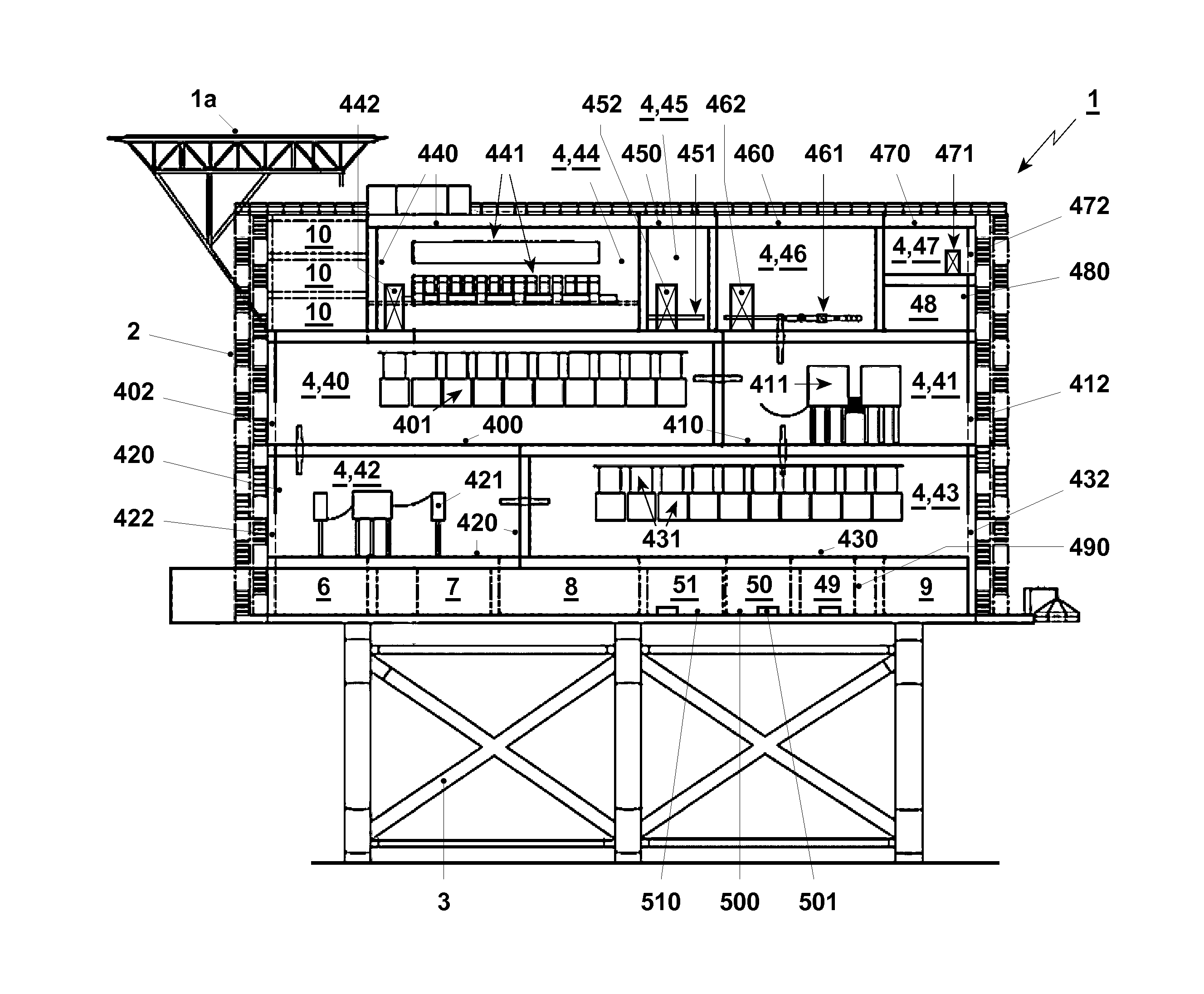
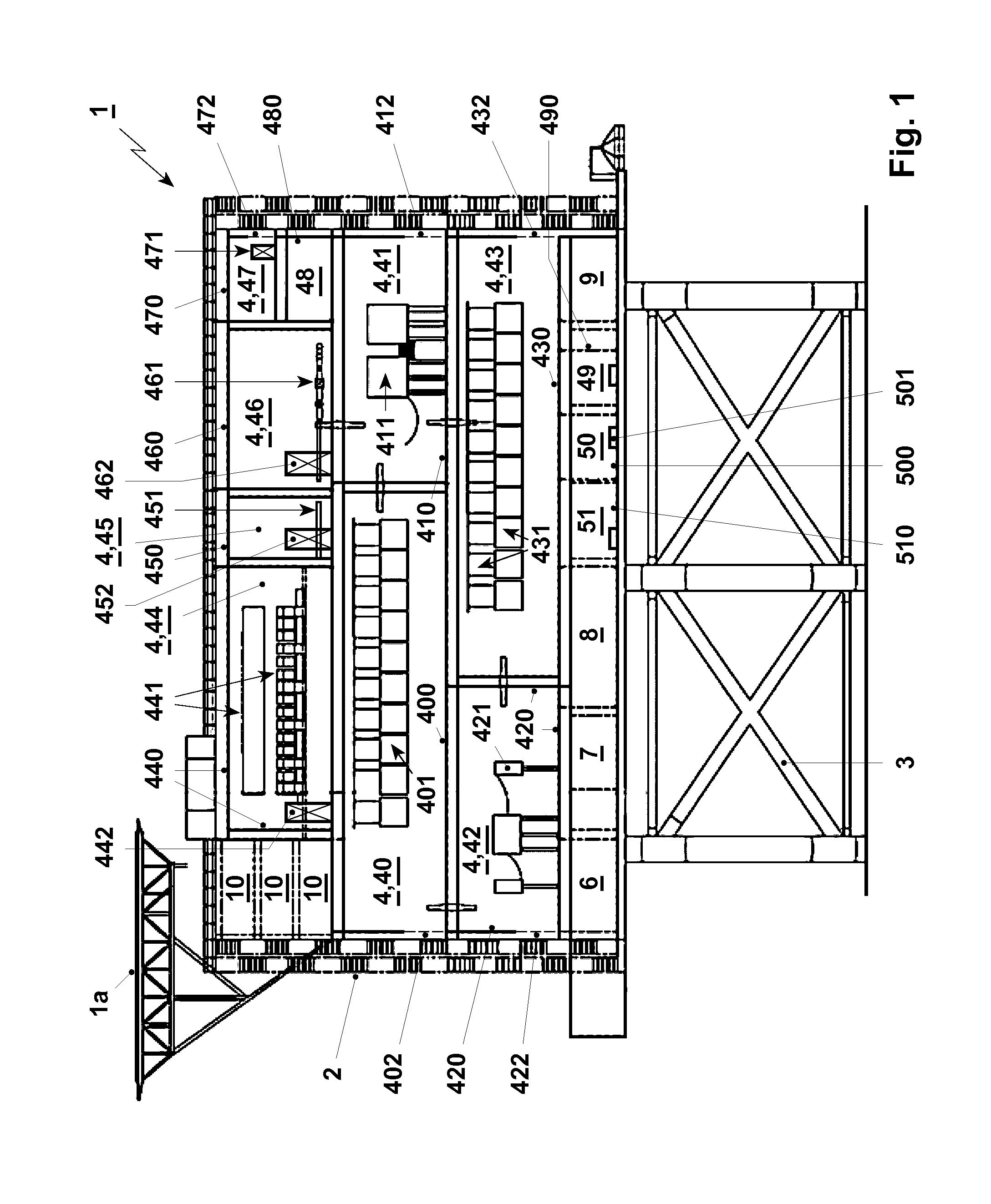
[0147]The HVDC offshore converter station shown in FIG. 1 corresponds to a conventional Dolwin converter station. It comprises a converter building 1 and a basement construction 3 on which the converter building 1 is arranged. The converter building 1 is spatially defined by a building wall 2 (e.g. with a staircase) which encloses a plurality of different rooms 4; 40-47, and may comprise further chambers or compartments 48-51.

[0148]Each of the rooms 4; 40-47 comprises a room wall 400, 410, 420, . . . 470 enclosing an interior space and may also be designated as a “hall”, which contain an electrical active part (401, 411, 421, . . . , 471), as discussed below. The room walls 400, 410, 420, . . . 470 are solid and have at least one opening, in particular door 402, 412, 422, 432; 442, 452, 462, 472, which is designed such that it allows a human to enter the interior space. The opening or openings or door or doors 402, 412, . . . , 472 is or are sealable such that the room walls 400, 41...


PUM


Abstract

A converter building including at least one room having a solid room wall enclosing an interior space and an electrical active part contained in the interior space, the room wall having at least one opening, which is designed such that it allows a human to enter the interior space. The opening is sealable, the room wall encloses the interior space in a gas-tight manner when the opening is sealed, and the interior space contains a dielectric insulation medium including a dielectric insulation component other than air.

Description

FIELD OF THE INVENTION[0001]The present invention relates to a converter building, as e.g. comprised in an HVDC station, an HVAC station or an HVAC / HVDC station, in particular an HVDC onshore or offshore station.BACKGROUND OF THE INVENTION[0002]HVDC (high-voltage, direct current) electric power transmission systems use direct current for the bulk transmission of electrical power. In particular for the transmission over long distances, HVDC systems suffer lower electric losses than alternating current (AC) systems.[0003]Electric energy generated in e.g. large wind farms is typically collected in AC offshore stations and transmitted to HVDC offshore stations where the conversion from AC to DC is performed.[0004]The platform of these stations comprises a converter building in which the respective electrical active parts are arranged. The size and weight of the converter building and of the platform, respectively, are related to the power capacity of the station.[0005]For example, the p...

Claims


Application Information

Patent Timeline
IPC IPC(8): H02B7/01G05D22/02G05D23/19G05D16/20
CPCH02B7/01G05D16/20G05D22/02G05D23/19H02B5/00H02B5/06
Inventor TERWIESCH, PETERMAHDIZADEH, NAVIDHYTTINEN, MATSERIKSSON, GORANKRAMER, AXELNORRGA, STAFFANPAUL, THOMAS ALFREDRIECHERT, UWESVENSSON, JANDIJKHUIZEN, FRANSMATHIAS, INGOLD
Owner HITACHI ENERGY SWITZERLAND AG
Learn More