
Measurement apparatus for measuring elasticity coefficient of coil spring

a technology of elasticity coefficient and measurement apparatus, which is applied in the direction of measurement devices, instruments, scientific instruments, etc., can solve the problem that the measurement period could be too long to meet the demand for quality control in mass production of electronic products

Inactive Publication Date: 2013-10-24
HONG FU JIN PRECISION IND (SHENZHEN) CO LTD +1
View PDF6 Cites 12 Cited by
  • Summary
  • Abstract
  • Description
  • Claims
  • Application Information

AI Technical Summary

Benefits of technology

The present patent is about a measurement apparatus for measuring the elasticity coefficient of a coil spring. The apparatus includes a workbench, mounting member, loading mechanism, deformation measuring mechanism, driving mechanism, and stress meter. The apparatus allows for quick and accurate measurement of the elasticity coefficient of a coil spring, which is important in the manufacturing process of electronic products. The apparatus is designed to be easily operated and maintained in a cost-effective manner.

Problems solved by technology

However, the measurement period could be too long to satisfy the demand for quality control in mass production of electronic products.

Method used


Image

  • Measurement apparatus for measuring elasticity coefficient of coil spring
  • Measurement apparatus for measuring elasticity coefficient of coil spring
  • Measurement apparatus for measuring elasticity coefficient of coil spring

Examples


Embodiment Construction

[0009]The present disclosure, including the accompanying drawings, is illustrated by way of examples and not by way of limitation. It should be noted that references to “an” or “one” embodiment in this disclosure are not necessarily to the same embodiment, and such references mean at least one.

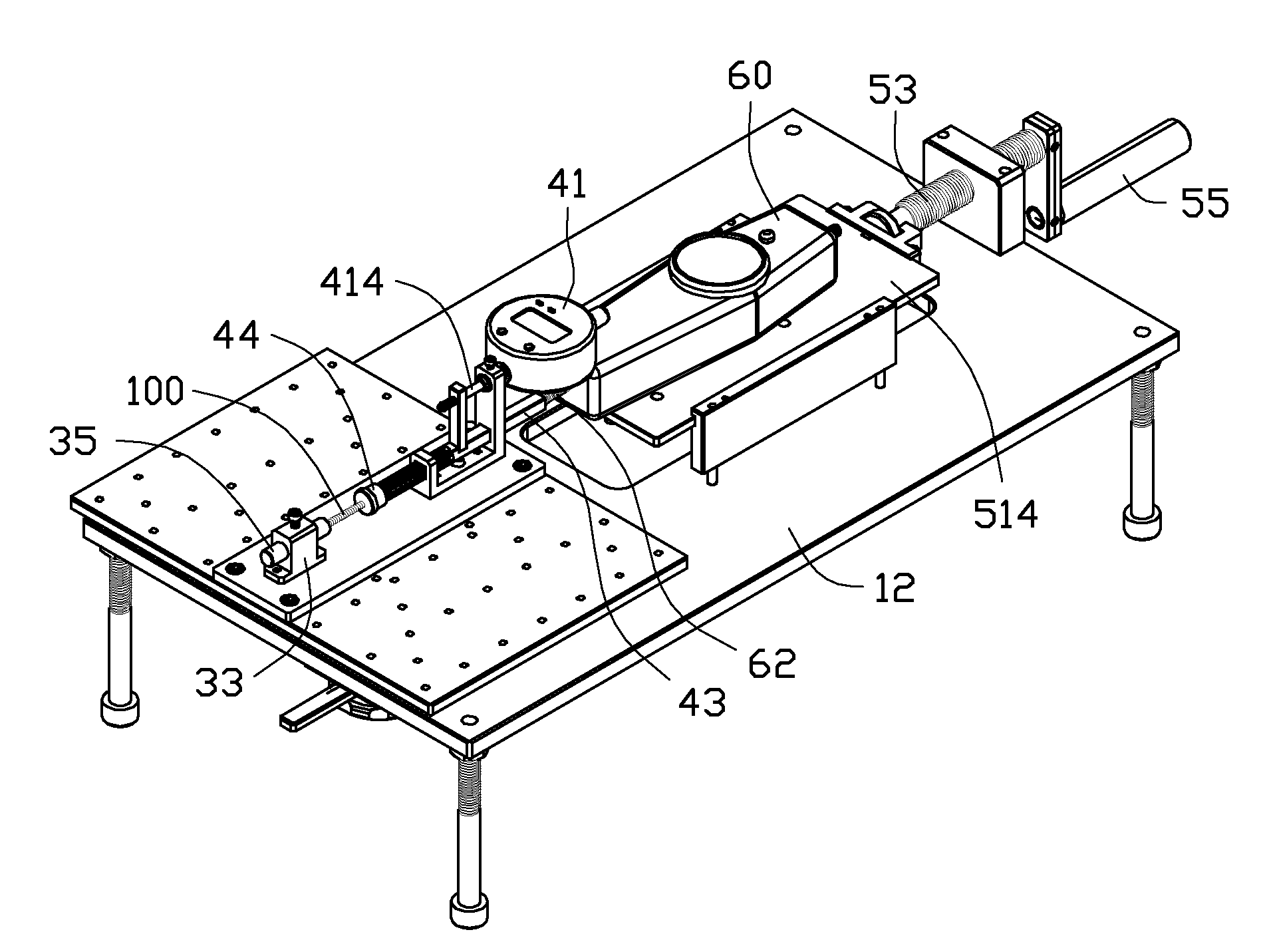
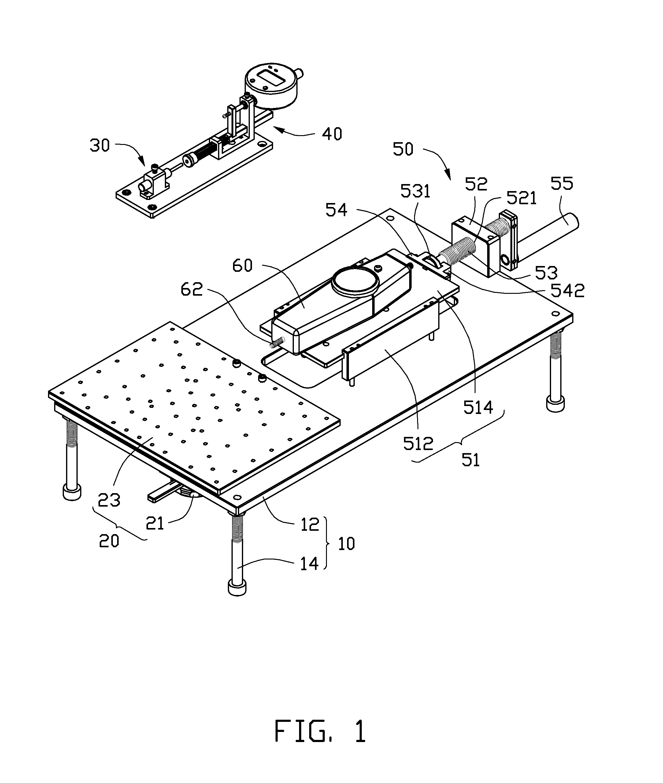
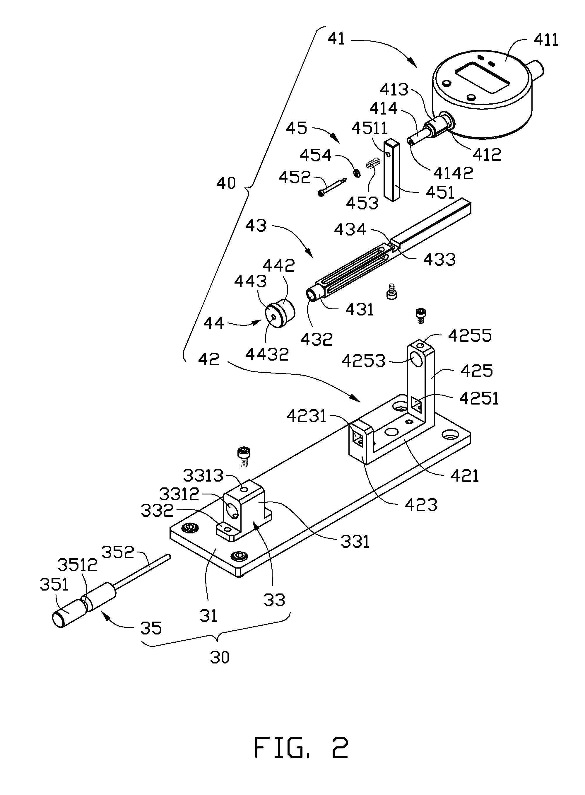
[0010]Referring to FIG. 1, an exemplary embodiment of a measurement apparatus is shown. The measuring apparatus includes a workbench 10, a mounting member 20, a loading mechanism 30, a deformation measuring mechanism 40, a driving mechanism 50, and a stress meter 60.

[0011]The workbench 10 includes a rectangular, horizontally-oriented support plate 12 and two support posts 14 respectively extending down from the four corners of the support plate 12.

[0012]The mounting member 20 includes an elevating member 21 mounted to a first end of the support plate 12, and a mounting plate 23 fixed to the elevating member 21, over the support plate 12. The elevating member 21 can drive the mounting plate 23 ...


PUM


Abstract

A measurement apparatus includes a workbench, a loading mechanism fixed to the workbench, a deformation measuring mechanism, and a stress meter. The deformation measuring mechanism includes a slide beam, and a displacement meter. The loading mechanism includes a guiding shaft extending through a to-be-tested coil spring. A measuring pole of the stress meter, the sliding beam, and the guiding shaft are coaxial. Opposite ends of the coil spring are respectively abutted the slide beam and the loading mechanism. A measuring pole of the displacement meter is connected to the sliding beam. When the stress meter slides towards the slide beam, the displacement of the detecting pole of the displacement member is equal to a change of a length of the coil spring, and recorded by the displacement meter, and a value of a force applied to the coil spring is recorded by the stress meter.

Description

BACKGROUND[0001]1. Technical Field[0002]The present disclosure relates to a measurement apparatus for measuring an elasticity coefficient of a coil spring.[0003]2. Description of Related Art[0004]Coil springs are widely used in electronic products. The elasticity coefficient of a coil spring, which is defined as the ratio of the stress applied to coil spring to the change of the length of the coil spring, is critical in determining the usage of the coil spring. Traditionally, the elasticity coefficient of a coil spring is measured in laboratory with a precision device. However, the measurement period could be too long to satisfy the demand for quality control in mass production of electronic products.BRIEF DESCRIPTION OF THE DRAWINGS[0005]Many aspects of the present embodiments can be better understood with reference to the following drawings. The components in the drawings are not necessarily drawn to scale, the emphasis instead being placed upon clearly illustrating the principles...

Claims


Application Information

Patent Timeline
IPC IPC(8): G01N3/00
CPCG01N3/08G01N2203/0292
Inventor ZHANG, BING-JUN
Owner HONG FU JIN PRECISION IND (SHENZHEN) CO LTD
Learn More