
Mechanical exfoliation apparatus

a technology of mechanical exfoliation and mechanical force, which is applied in the direction of synthetic resin layered products, chemical/physical processes, natural mineral layered products, etc., can solve the problems of system components required, failure to describe specific mechanical force type and size,

Active Publication Date: 2013-10-03
XG SCI
View PDF8 Cites 30 Cited by
  • Summary
  • Abstract
  • Description
  • Claims
  • Application Information

AI Technical Summary

Benefits of technology

The invention is an apparatus for mechanically exfoliating particulate materials using a multi-axis approach. The apparatus includes a support frame, a motor mount, and a main drive shaft with a driven flywheel mounted on it. The support frame has a non-stationary plate surmounted on it by shock absorbing mounts. There are also cams and a stabilizer drive mechanism. The apparatus can be used to mechanically exfoliate particulate materials with a basil plane. The technical effects of the invention include improved efficiency and control in exfoliating particulate materials, as well as reduced wear and tear on the equipment.

Problems solved by technology

Prior art methods have described the results, however, they have failed to describe the specific mechanical forces in type and size, and the system of components required for success.

Method used


Image

  • Mechanical exfoliation apparatus
  • Mechanical exfoliation apparatus
  • Mechanical exfoliation apparatus

Examples


Embodiment Construction

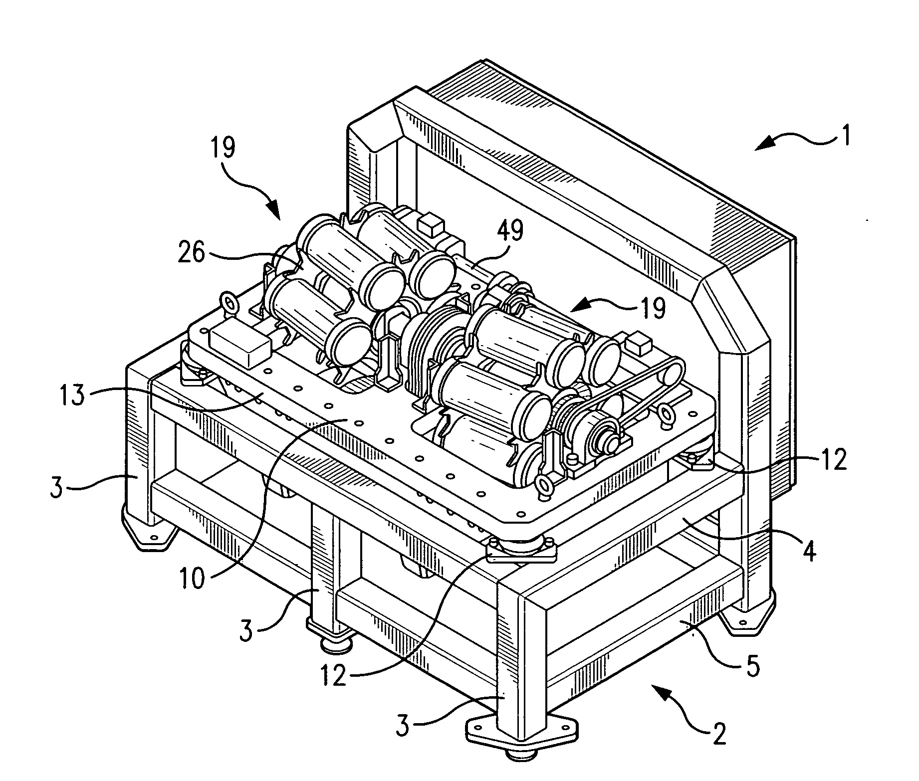
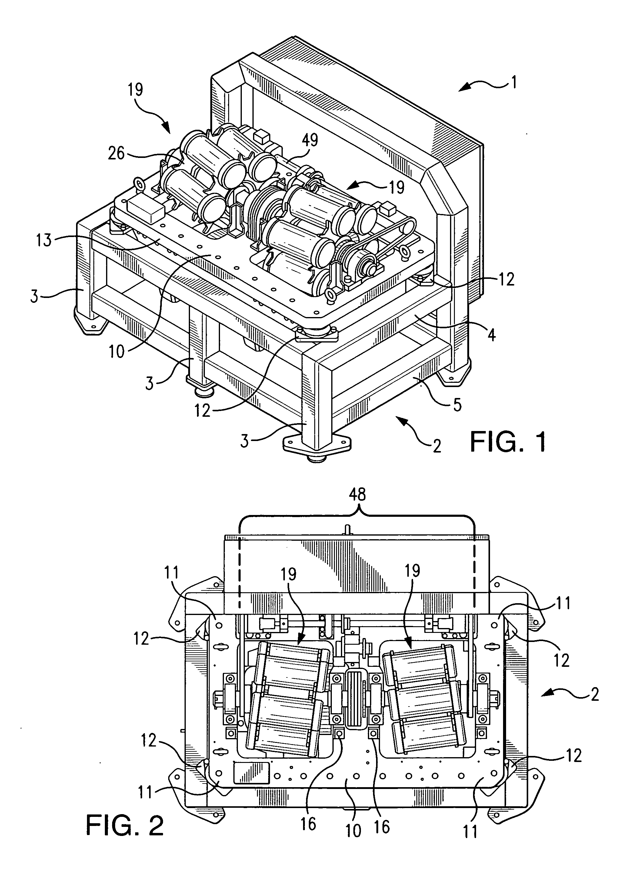
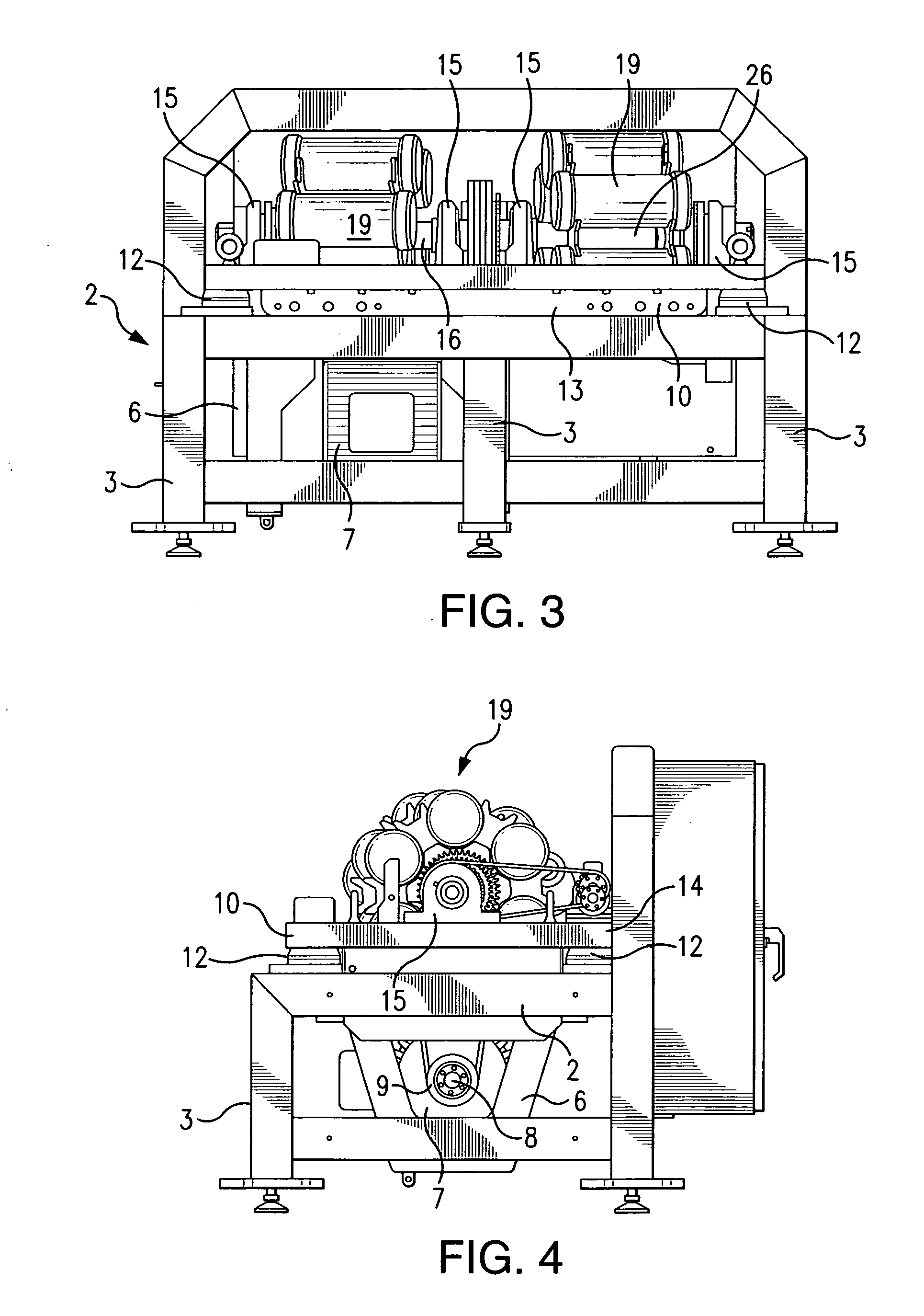
[0063]Turning now to FIG. 1, there is shown a full top view in perspective of the apparatus 1 of this invention. FIG. 2 is a full top view of the apparatus, FIG. 3 is a full front view of the apparatus, and FIG. 4 is a full end view of the apparatus of this invention from the end opposite of the motor mounting. The Figures should be consulted for an understanding of the information that follows.

[0064]In FIGS. 1, 2, 3, and 4, there is shown a framework 2 for supporting the working components of this invention and thus there is shown the legs 3 of the framework 2, the upper bar frame 4, and a lower bar frame 5.

[0065]With reference to FIG. 5, there is shown a motor mount 6, mounted on the lower bar from 5, on which there is mounted a motor 7, also shown in FIG. 3 more clearly. The motor 7 is the main drive mechanism for the apparatus 1. The motor has a motor drive shaft 8, shown in FIG. 4, and attached to this drive shaft 8 is a driven flywheel 9.

[0066]As shown clearly in FIGS. 1, 2, a...


PUM

PropertyMeasurementUnit
specific gravityaaaaaaaaaa
sizeaaaaaaaaaa
sizeaaaaaaaaaa

Abstract

Apparatus to deliver predetermined forces, containers to hold particulate material and media, media, and the associated parameters for operating such equipment along with methods and compositions provided by the apparatus and methods.

Description

BACKGROUND OF THE INVENTION[0001]There are several inventions and efforts to produce graphene chemically, thermally, and mechanically. Exfoliation involves the removal of the layers on the graphite's outermost surface. Ball milling is the most used of these methods, and this method involves milling the graphene in a closed container using various milling media. The ball mill moves in only one direction, that is, rotational on a horizontal axis. Prior art methods have described the results, however, they have failed to describe the specific mechanical forces in type and size, and the system of components required for success.[0002]The applicant is aware of WO2011006814 that deals with a wet process for providing particulate materials.BRIEF DESCRIPTION OF THE INVENTION[0003]The instant invention, in one embodiment, deals with an apparatus that includes a system of components to mechanically exfoliate particulate materials using a multi-axis approach. In this embodiment, layers of part...

Claims


Application Information

Patent Timeline
Patent Type & Authority Applications(United States)
IPC IPC(8): B24B1/00F16C3/02F16H55/02F16H55/17C01B31/00B32B5/16F16H37/06F16H53/00B82Y30/00B82Y40/00
CPCB82Y30/00B82Y40/00C01B31/0469C01P2006/12Y10T74/19949Y10T74/19051Y10T428/2991Y10T74/2101Y10T74/1987C01B32/19B02C17/14B02C17/186B02C17/24B01F31/25C01B32/225C01B32/182B01F31/70B01F31/201C01B2204/02C01B2204/04C01B2204/32F16H1/20F16H53/02F16H55/17F16H2055/176F16C3/02F16H37/065F16H53/00F16H1/22
Inventor MURRAY, SCOTT L.PEYTON, JIM L.MORRIS, KOREY
Owner XG SCI
Learn More