Pumping system for evacuating gas from a plurality of chambers and method for controlling the pumping system

a technology of pumping system and gas evacuation chamber, which is applied in the direction of pump control, non-positive displacement fluid engine, pump control, etc., can solve the problems of only being able to adapt the noise reduction to existing possibilities, increasing the energy consumption and associated, and reducing the efficiency of the pumping system, so as to achieve simple throttle orifice, simple structure, and constant throughput

Inactive Publication Date: 2013-10-03
PFEIFFER VACUUM GMBH
View PDF6 Cites 10 Cited by
  • Summary
  • Abstract
  • Description
  • Claims
  • Application Information

AI Technical Summary

Benefits of technology

The patent text describes a vacuum system that has separate chambers connected to each other and operates at different vacuum levels. The system includes valves to control the flow of gas between the chambers. The vacuum pumps used in the system are capable of handling high discharge pressures. A transverse constriction is used to relieve one of the vacuum pumps and ensure the other pump can maintain a certain level of discharge pressure. The technical effects of this system include improved vacuum control and better adaptation to different process conditions.

Problems solved by technology

The greater is the gas load a pump should handle, the higher is the energy consumption and the associated therewith cooling requirements, and electrical and mechanical losses caused by gas friction.
In actual cases, the gas loads and vacuum differ greatly from chamber to chamber, and adaptation of the noise reduction to existing possibilities while maintaining the desired process characteristics, is difficult and only possible when considering the balance of interests.

Method used


Image

  • Pumping system for evacuating gas from a plurality of chambers and method for controlling the pumping system
  • Pumping system for evacuating gas from a plurality of chambers and method for controlling the pumping system
  • Pumping system for evacuating gas from a plurality of chambers and method for controlling the pumping system

Examples


Embodiment Construction

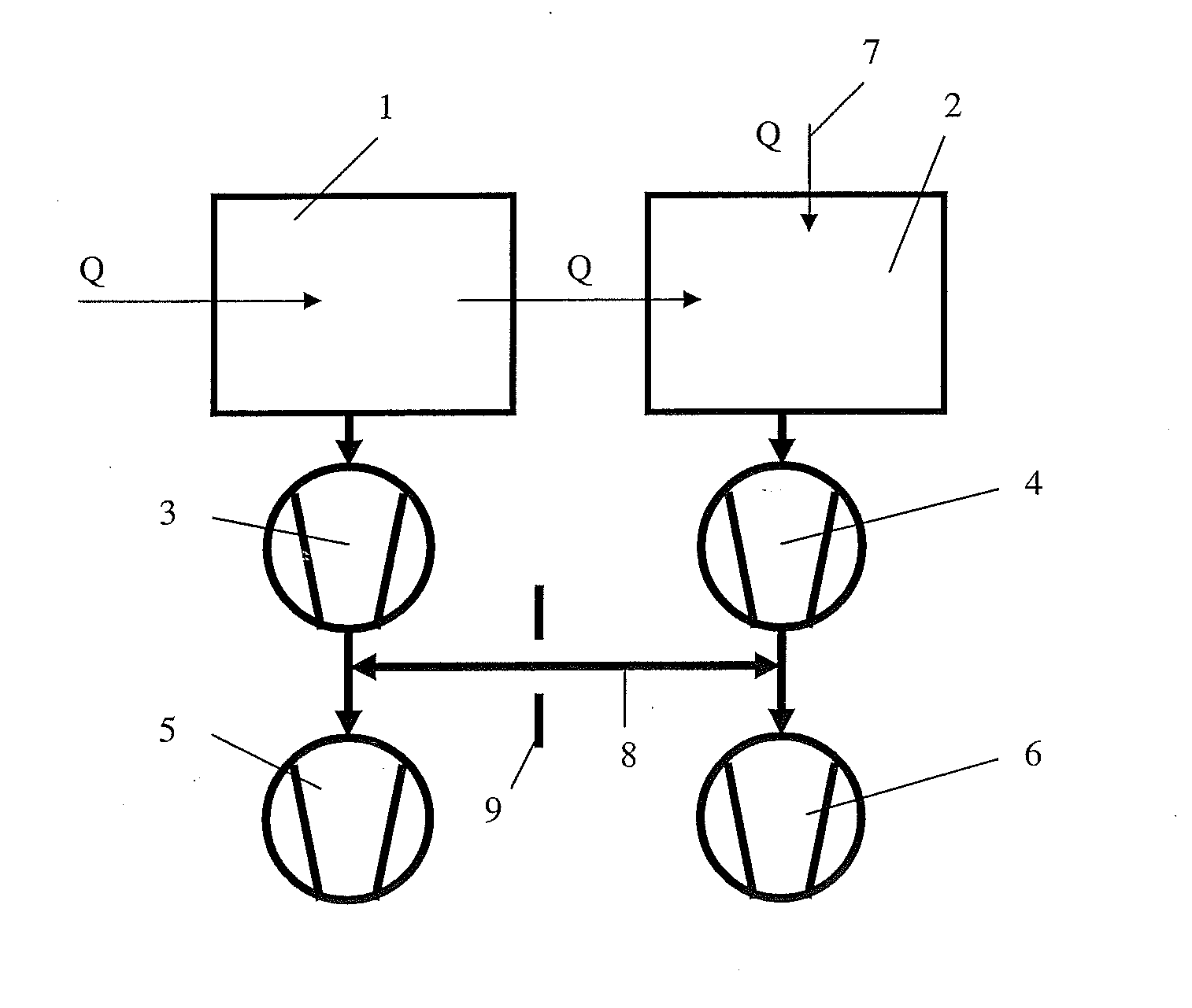
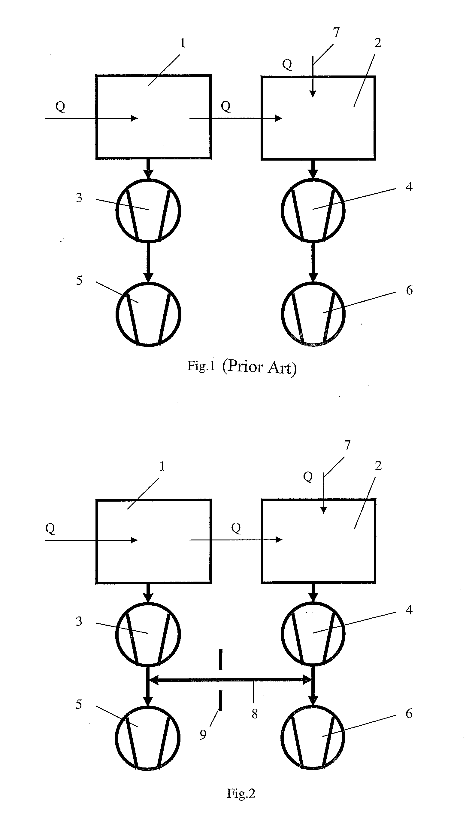
[0037]FIG. 1 shows a prior art pumping system that has two to-be-evacuated chambers 1 and 2. A turbomolecular pump 3 is associated with the chamber 1, and a turbomolecular pump 4 is associated with the chamber 2.

[0038]The turbomolecular pump 3 is supported by a fore-vacuum pump 5, and the turbomolecular pump 4 is supported by fore-vacuum pump 6. The drawback of the prior art pumping system consists in that the turbomolecular pump 3 should maintain a predetermined pressure in the chamber 1, and the turbomolecular pump 4 should maintain a predetermined pressure in the chamber 4. Accordingly, the pumps 3, 4, 5, 6 should be correspondingly capable of performing this task. This means that they must have a required pumping capacity under network voltage and frequency condition for a particular region.

[0039]Q designates a gas flow. The chambers 1 and 2 are connected with each other. With different pressures in chambers 1 and 2, there exists a gas flow Q between the two chambers. In the cha...


PUM


Abstract

A pumping system for evacuating gas from a plurality of chambers, includes at least one turbomolecular pump, at least two fore-vacuum pumps, at least one connection conduit extending between the at least two fore-vacuum pumps. and at least one transverse constriction for at least one of reducing and regulating gas flow.

Description

BACKGROUND OF THE INVENTION[0001]1. Field of the Invention[0002]The invention relates to a pumping system for evacuating gas from a plurality of chambers and to a method of controlling the pumping system.[0003]2. Description of the Prior Art[0004]Practically, the entire system consists of one or more vacuum chambers (recipients). These chambers can be used separately, however, they may be connected, at least partially, with each other. In this case, at a set pressure difference, a substantial gas flow takes place therebetween through an opening formed in a common wall between two process chambers or through a tubular conduit connecting the chambers. One or several chambers can also be subjected to gas loads which can also result from connection with the chamber environment (atmosphere), from gas loads transmitted from upstream-located chambers, from otherwise generated, mostly process-dependent, gas flows, and also from admitted inert or process gases such as helium, from desorption...

Claims


Application Information

Patent Timeline
IPC IPC(8): F04B23/08
CPCF04B23/08F04D27/003F04D19/046F04D19/042F04D25/16F04D27/0269F04D27/0253F04D27/009
Inventor BURGGRAF, THORSTENHOFMANN, JANSTOLL, TOBIAS
Owner PFEIFFER VACUUM GMBH
Why Eureka
Try Eureka