
Display device

Inactive Publication Date: 2013-08-15
SHARP KK
View PDF4 Cites 27 Cited by
  • Summary
  • Abstract
  • Description
  • Claims
  • Application Information

AI Technical Summary

Benefits of technology

The invention is a display that can show a clear image in low light levels while using less power.

Problems solved by technology

Especially, a reflection-type liquid crystal display device utilizing external light can provide color display with high visibility in a bright environment but has a problem of not easily providing color display with high visibility in a dark environment.

Method used


Image

  • Display device
  • Display device
  • Display device

Examples


Embodiment Construction

[0046]Hereinafter, display devices 100A through 100K in embodiments according to the present invention will be described with reference to the drawings. The display devices 100A through 100K in the embodiments according to the present invention are liquid crystal display devices. Each of these liquid crystal display device is of a reflection type, a transmission type or a see-through type.

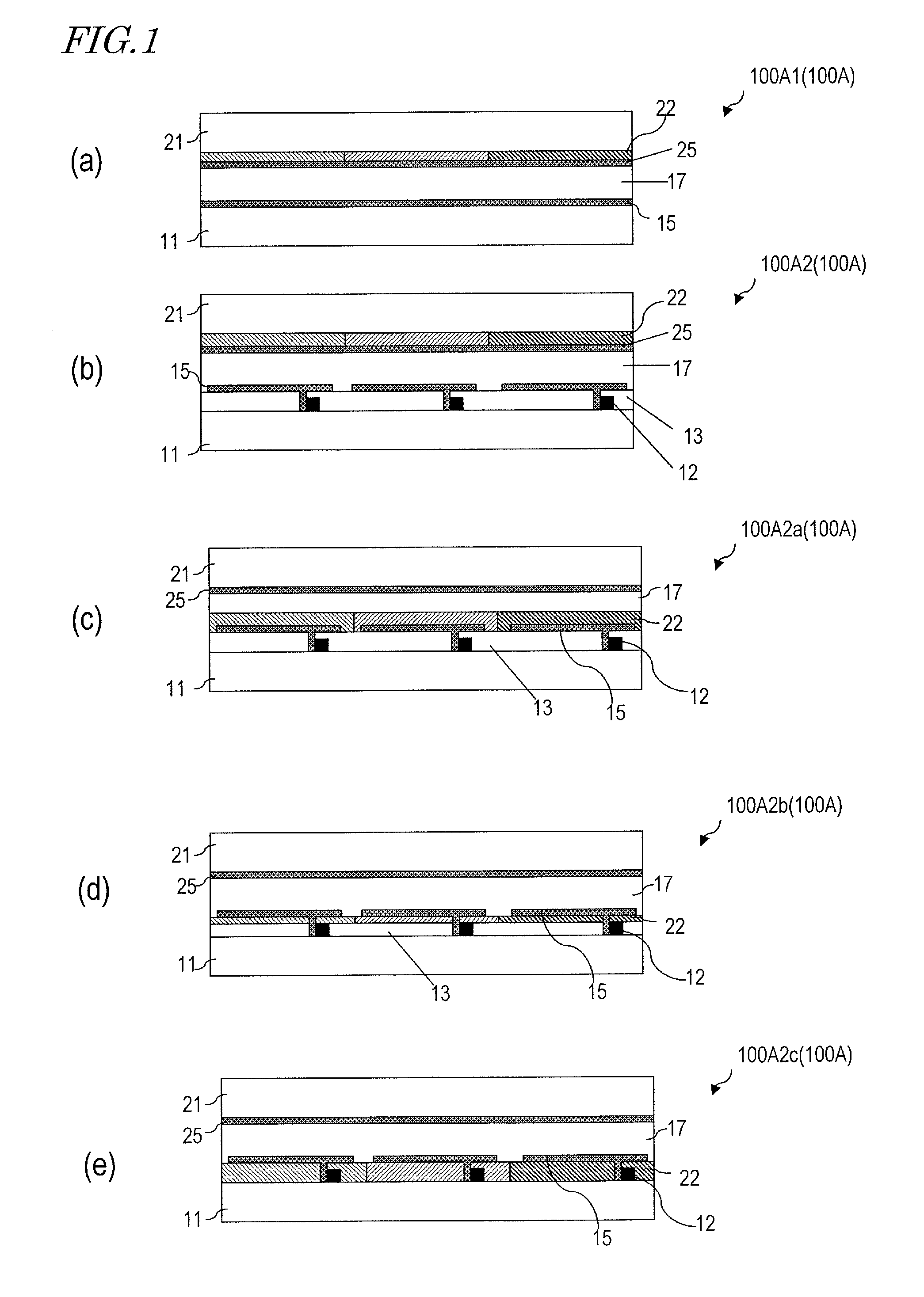
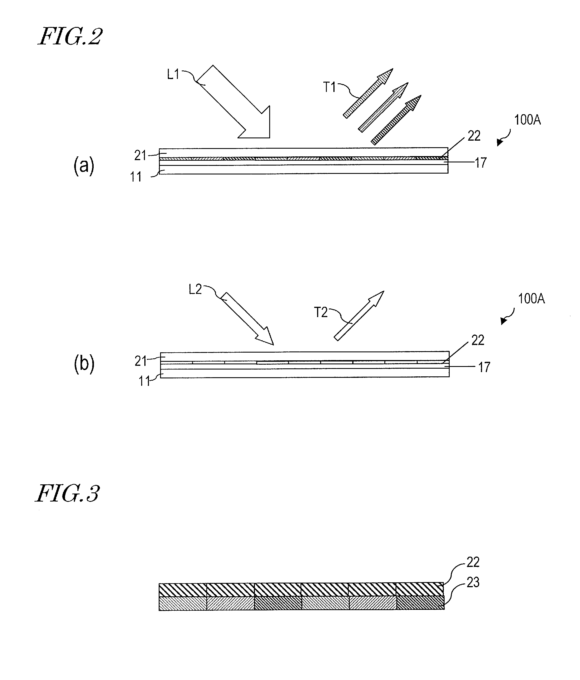
[0047]With reference to FIGS. 1 through 3, the display device 100A in an embodiment according to the present invention will be described.

[0048]FIGS. 1(a) through 1(e) are schematic cross-sectional views of the display device 100A. The display device 100A is a reflection-type liquid crystal display device.

[0049]A display device 100A1 shown in FIG. 1(a) includes a first substrate (e.g., glass substrate) 11, a second substrate (e.g., glass substrate) 21 facing the first substrate 11, and a light modulating layer 17 provided between the first substrate 11 and the second substrate 21. On the first subst...


PUM

PropertyMeasurementUnit
Currentaaaaaaaaaa
Electric potential / voltageaaaaaaaaaa
Lightaaaaaaaaaa

Abstract

A display device (100A) according to the present invention includes a first substrate (11), a second substrate (21), and a light modulating layer (17) provided between the first substrate (11) and the second substrate (21). The first substrate (11) or the second substrate (21) has a layer (22) provided thereon containing a photochromic compound.

Description

TECHNICAL FIELD[0001]The present invention relates to a display device, and specifically, a liquid crystal display device.BACKGROUND ART[0002]Color liquid crystal display devices widely used today include color filters in correspondence with pixels. Typically, color filters corresponding to three primary colors of light of red (R), green (G) and blue (B) are arrayed in a prescribed pattern in correspondence with pixels. The color display pixels include a plurality of primary color pixels, and typically include pixels of three colors of R, G and B.[0003]In general, a liquid crystal display device includes a pair of substrates and a liquid crystal layer provided therebetween. The above-described plurality of color filters arrayed in accordance with the pixels are formed in either one of the substrates. In a liquid crystal display device, for example, a liquid crystal layer is formed between a TFT substrate including circuit elements such as pixel electrodes, TFTs (Thin Film Transistor...

Claims


Application Information

Patent Timeline
IPC IPC(8): G02F1/1335
CPCG02F1/1334G02F1/133514G02F1/133617G02F1/133528G02F2201/086G02F1/1335G02F2001/133616G02F1/133616
Inventor SATOH, EIJIMIYATA, AKIODEGUCHI, KAZUHIRO
Owner SHARP KK
Learn More