
Display device

a technology of liquid crystal display panel and display panel, which is applied in the field of display panel, can solve the problems of unbalance between writing periods of pixels of a plurality, and luminance difference may occur between the divided regions of the liquid crystal display panel, and achieve the effect of preventing luminance differen

Active Publication Date: 2013-08-15
JAPAN DISPLAY INC
View PDF2 Cites 8 Cited by
  • Summary
  • Abstract
  • Description
  • Claims
  • Application Information

AI Technical Summary

Benefits of technology

The present invention aims to prevent luminance differences between different regions of a display panel caused by asynchronous display signals input to multiple timing controllers in a display device. This is achieved using a technique that ensures synchronization between the display signals and the divided display panel. The technical effect of this invention is to create a more uniform and consistent display across the entire panel, improving the overall quality of the display.

Problems solved by technology

However, asynchronization between the display signals which are respectively independently input to the timing controllers from the external device is reflected on an output signal, which causes unbalance between writing periods for pixels of a plurality of regions of the liquid crystal display panel, and, as a result, a luminance difference may occur between the divided regions of the liquid crystal display panel.

Method used


Image

  • Display device
  • Display device
  • Display device

Examples


embodiment

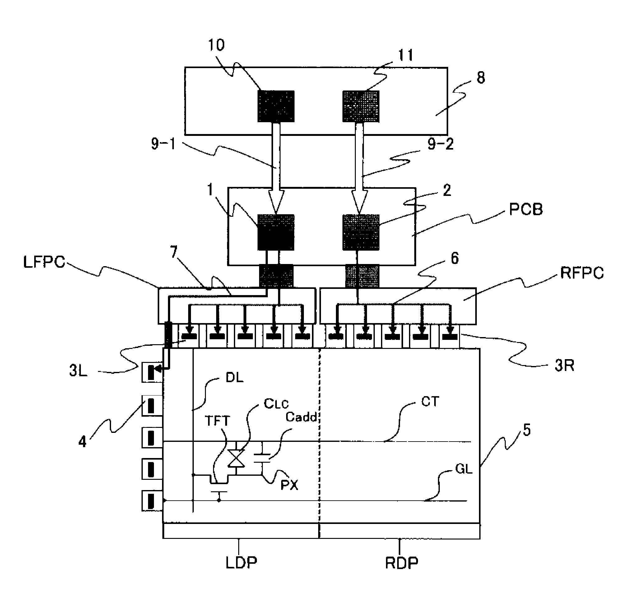
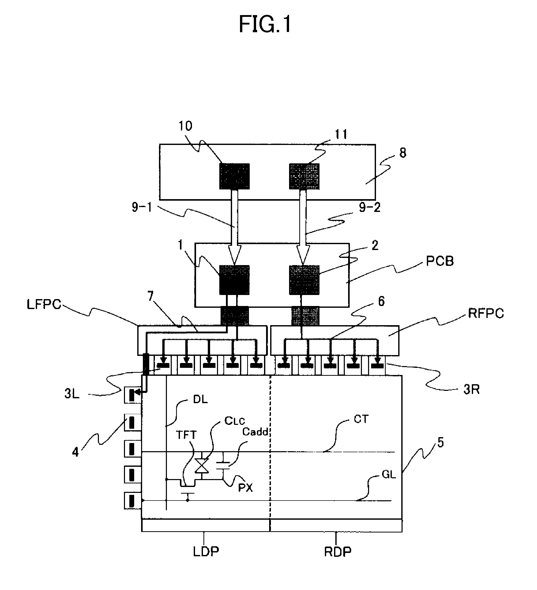
[0038]FIG. 1 is a block diagram illustrating a schematic configuration of a liquid crystal display device according to an embodiment of the present invention.

[0039]In the liquid crystal display device of the present embodiment, a plurality of drain drivers 3L and 3R are disposed at one side of the longer sides of a liquid crystal display panel 5, and, a plurality of gate drivers 4 are disposed at one side of the shorter sides of the liquid crystal display panel 5.

[0040]The liquid crystal display panel 5 includes a plurality of pixels formed in a matrix. Each pixel is disposed in an intersection region between two adjacent signal lines (drain signal lines DL or gate signal lines GL) and two adjacent signal lines (the gate signal lines GL or the drain signal lines DL).

[0041]Each pixel has a thin film transistor TFT, a source electrode of the thin film transistor TFT of each pixel is connected to a pixel electrode PX, and a liquid crystal layer is provided between the pixel electrode P...


PUM


Abstract

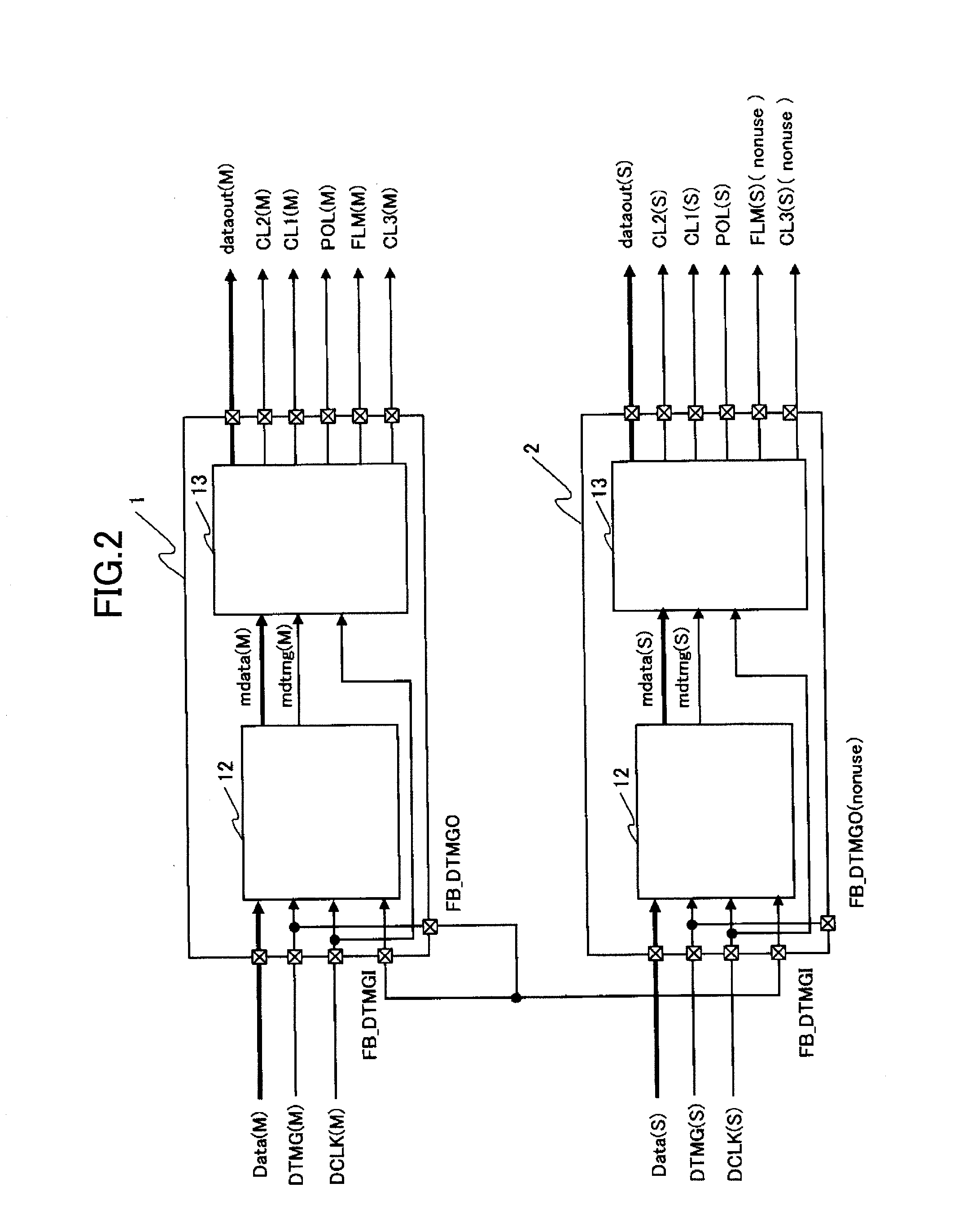
Each of a plurality of timing controllers has a synchronization reference signal output terminal from which a synchronization reference signal is output and a synchronization reference signal input terminal to which the synchronization reference signal is input. A master timing controller outputs a predetermined signal of display signals which are input from an external device, from the synchronization reference signal output terminal of the master timing controller as the synchronization reference signal, and the synchronization reference signal is input to the synchronization reference signal input terminals of the master timing controller and a slave timing controller. Accordingly, a luminance difference can be prevented from occurring between divided regions of a display panel due to asynchronization between display signals input to respective timing controllers in a display device in which a plurality of timing controllers are used and the display panel is divided into a plurality of regions.

Description

CROSS-REFERENCE TO RELATED APPLICATION[0001]The present application claims priority from Japanese application JP2012-027454 filed on Feb. 10, 2012, the content of which is hereby incorporated by reference into this application.BACKGROUND OF THE INVENTION[0002]1. Field of the InventionTechnical Field[0003]The present invention relates to a display device, and particularly to a technique suitable to be applied to a driving circuit for driving a display panel of an ultra-high resolution.[0004]2. Description of the Related Art[0005]A TFT (Thin Film Transistor) type liquid crystal display device is widely used as a display device of a PC or the like. This liquid crystal display device includes a liquid crystal display panel, driving circuits for driving the liquid crystal display panel, and a control circuit for controlling the driving circuits.[0006]In addition, as the liquid crystal display device, there is a liquid crystal display device in which a liquid crystal display panel is divi...

Claims


Application Information

Patent Timeline
Patent Type & Authority Applications(United States)
IPC IPC(8): G09G3/36
CPCG09G2310/08G09G3/3685G09G2320/0233
Inventor OOHIRA, TOMOHIDETOKITA, MASAHIROYAMAGISHI, YASUHIKO
Owner JAPAN DISPLAY INC
Learn More