
Variable speed electric machine and method for generating electric energy

a variable speed electric machine and variable speed technology, applied in the field of electric machines, can solve the problems of high cost of power converters, variable wind speed experienced by rotor blades, and the inability to use and achieve the effect of reducing the cost of utilizing only power converters to balance the variation in input speed in most wind applications

Active Publication Date: 2013-08-15
GENERAL ELECTRIC CO
View PDF5 Cites 12 Cited by
  • Summary
  • Abstract
  • Description
  • Claims
  • Application Information

AI Technical Summary

Benefits of technology

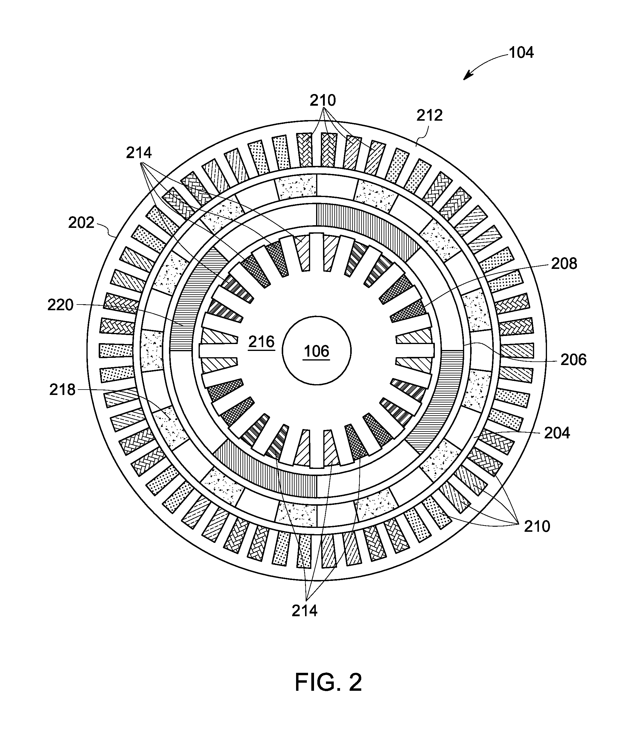
The invention relates to an electric machine that can generate constant frequency electric energy from wind energy. The machine includes an outer stator with field windings and a modulator outer rotor, which is coupled to an input shaft. The machine also has an inner stator with field windings and a permanent magnet inner rotor as a rotor. The outer stator, modulator outer rotor, inner stator, and inner rotor are magnetically coupled to each other to maintain a constant frequency of electric energy generation at the inner stator. The system also includes a power converter to transfer energy of a pre-determined frequency from the modulator outer rotor to the inner stator through the magnetic coupling. The method includes selectively energizing the field windings of the outer stator and controlling the electric signal to maintain constant frequency of electric energy generation at the inner stator. The technical effects of this invention include the ability to generate constant frequency electric energy from wind energy and improved efficiency in energy conversion.

Problems solved by technology

Generating energy through such means has its own set of disadvantages that include the variability of wind speed experienced by the rotor blades.
Power converters are expensive, since they involve electronic equipment that is manufactured to precision.
Hence, utilizing only power converters to balance the variation in input speed has proven to be expensive in most wind applications.

Method used


Image

  • Variable speed electric machine and method for generating electric energy
  • Variable speed electric machine and method for generating electric energy
  • Variable speed electric machine and method for generating electric energy

Examples


Embodiment Construction

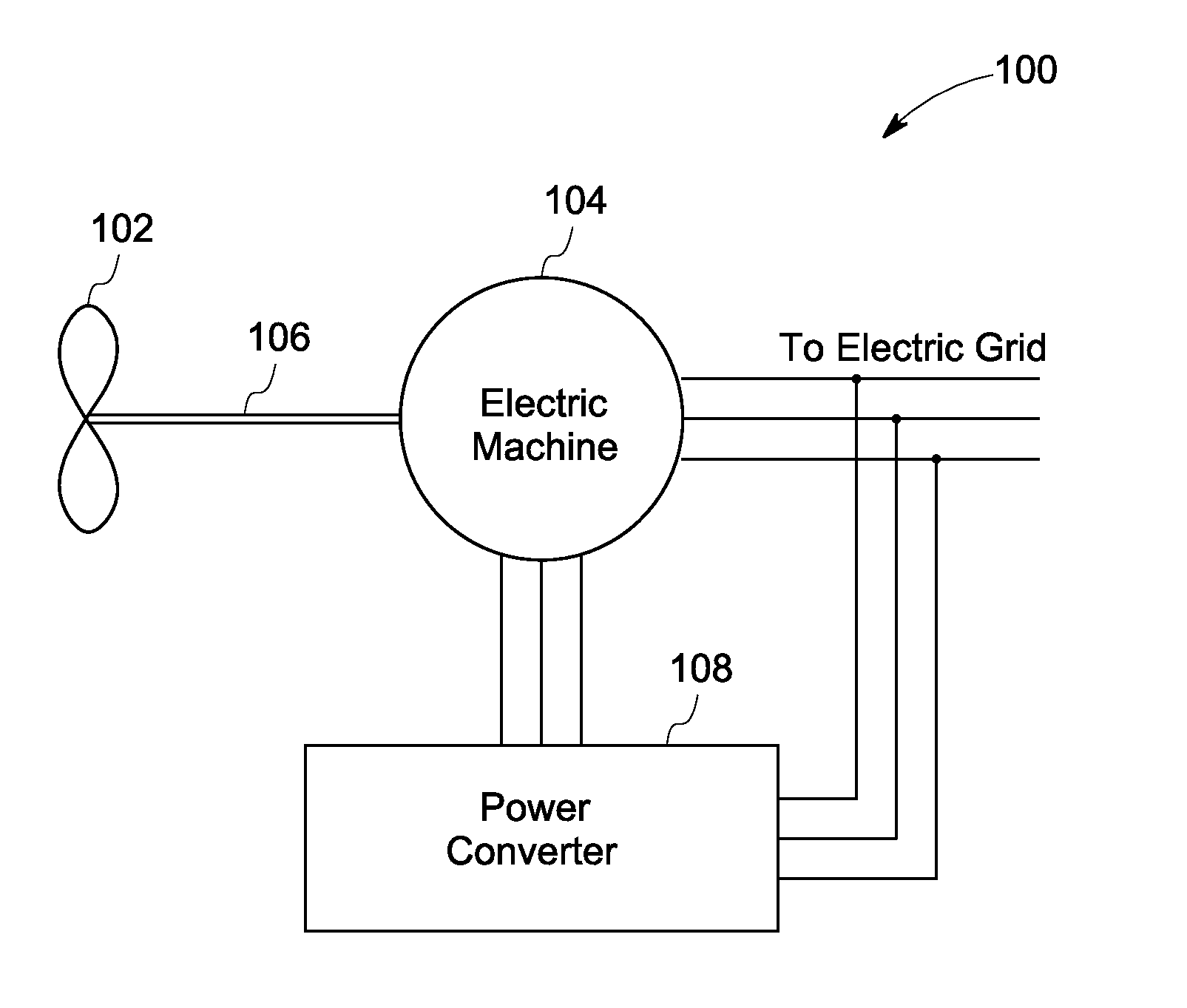
[0014]Reference will be made below in detail to exemplary embodiments of the invention, examples of which are illustrated in the accompanying drawings. Wherever possible, the same reference numerals used throughout the drawings refer to the same or like parts.

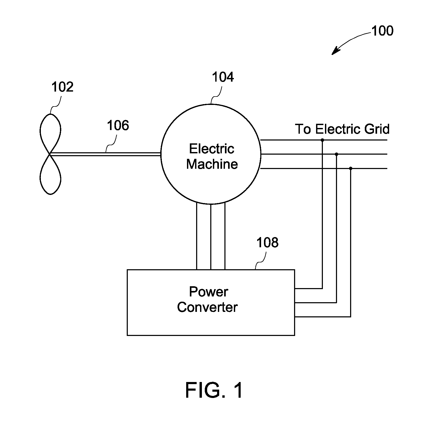
[0015]Embodiments of the invention described herein relate to an electric machine that can generate constant frequency electric energy when an input provided to the electric machine is of varying frequency / speed. The input to the electric machine, in some embodiments, can be rotational energy obtained from wind of varying speed experienced by rotors of a wind turbine. The electric machine has an inner and an outer stator, which have a first set of field windings and a second set of field windings respectively. The outer stator, in one embodiment, is employed as a control stator. The inner stator is connected to an electric grid to supply the generated electric energy for consumption. The electric machine also includes a modulat...


PUM


Abstract

A variable speed electric machine and a method for generating electric energy is provided. The electric machine includes an outer stator with a first set of field windings. Further, the electric machine includes a modulator outer rotor that is concentric and is located proximate to the outer stator. The modulator outer rotor is operatively coupled to an input shaft. Furthermore the electric machine includes a permanent magnet inner rotor concentric to the modulator outer rotor. The electric machine also includes an inner stator with a second set of field windings. The inner stator is concentric to the inner rotor and is operatively coupled to an electric grid. The outer stator, the modulator outer rotor, inner stator and the inner rotor are magnetically coupled with each other so as to maintain a constant electric frequency at the inner stator.

Description

BACKGROUND[0001]The present invention relates, generally, to the field of electric machines, and, in particular, to a variable speed electric machine and method for generating electric energy.[0002]Energy demands of the world today have risen above the supply of energy from naturally existing sources like fossil fuels. Conventional energy generation methods include combustion of fossil fuels to create energy that is then transformed into electric energy. Renewable forms of energy, such as solar power, and wind power, have become increasingly important to meet the ever increasing energy demands. Wind energy is utilized to generate electric energy with the help of a turbine that, in its simplest form, has a rotor with rotor blades and a generator shaft coupled to the rotor. The wind energy causes the rotor to rotate and in turn rotate the generator shaft to generate electric energy through the generator configuration. Generating energy through such means has its own set of disadvantag...

Claims


Application Information

Patent Timeline
Patent Type & Authority Applications(United States)
IPC IPC(8): H02P9/48F03D9/00H02P9/26H02K23/60
CPCH02K16/00H02P9/26H02P9/42H02P9/40H02P9/48
Inventor HEMMELMANN, JAN ERICHSHAH, MANOJ RAMPRASAD
Owner GENERAL ELECTRIC CO
Learn More