
Stamp press

Inactive Publication Date: 2013-08-15
KONIK HENRY STEPHEN
View PDF2 Cites 20 Cited by
  • Summary
  • Abstract
  • Description
  • Claims
  • Application Information

AI Technical Summary

Benefits of technology

The patent text explains that traditional manual methods of stamping require a lot of practice and large printing presses are expensive. Many people who stamp for fun avoid using large and complex stamps. The solution proposed in the patent is a printing apparatus that overcomes these problems.

Problems solved by technology

However, several problems are encountered as complexity or size of the transfer image and location of the stamp onto the paper surface.
Amongst these problems are ink coverage that may be less-than-complete, resulting in a stamped image that is also incomplete or with varied ink density.
Mainly, this issue is attributed to ink pad distribution inconsistencies caused by ink roller unevenness (pressure or ink coverage), or a creator's own inability to judge the ink coverage of the stamp.
Furthermore, manually applied pressure to the stamp may be uneven across the total area of a stamp-paper interface, thus resulting in the stamped image density that varies according to local pressure applied.
For example, the left side of a stamp image may be lighter than the right side if creator applied more pressure to the right side of the stamp, hence, manually applying proper pressure evenly across a large stamp, often requiring much practice or trial-and-error, thereby requiring large quantities of ink and supplies.
In addition, the stamp itself may be uneven across its inking surface, thus the density of applied ink may be proportional to the relative height of the stamp surface to paper.
Said problem is exacerbated by the use of large stamps, wherein tight in-plane tolerances must be met over proportionally large area.
Also, by manually positioning the stamp via measuring the location on the card or print medium using a ruler or other measuring device and marking its location within an area that the image is desired, this is very time consuming.
Another problem appears when a repetitive operation is required and thus consistency in the image produced.
Again, greeting card creator must address aforementioned problems, which often require much practice or trial-and-error, thereby resulting in the use of large quantities of ink and supplies.
While said printing method works well for professional stamper, many stamping hobbyists cannot afford the often-bulky and precision-made printing press.
Although inexpensive versions of printing presses are commercially available, many of these products are prone to image quality issues that are evident with manual stamping methods; i.e., if ink distribution is uneven across a stamp, the resulting stamped image will also be uneven.
This problem is compounded by the use of large or complex stamps.
Although this manual method can ameliorate the problems of uneven stamp surface and provide, with practice, a more-consistent image, it does not eliminate them.
Several problems still remain.
The first lies within the re-inking of a stamp—if required to correct a spotty image—is not practical (paper and stamp would likely be misaligned on second printing).
For example, centering a small image on a large card can be rather difficult.
Lastly, the method is still get-it-right-the-first-time technique, in which inadequate pressure may result in the rejection of the finished product.
In accordance with one embodiment, the traditional manual methods require much practice, and large printing presses are expensive.

Method used


Image

  • Stamp press
  • Stamp press
  • Stamp press

Examples


first embodiment

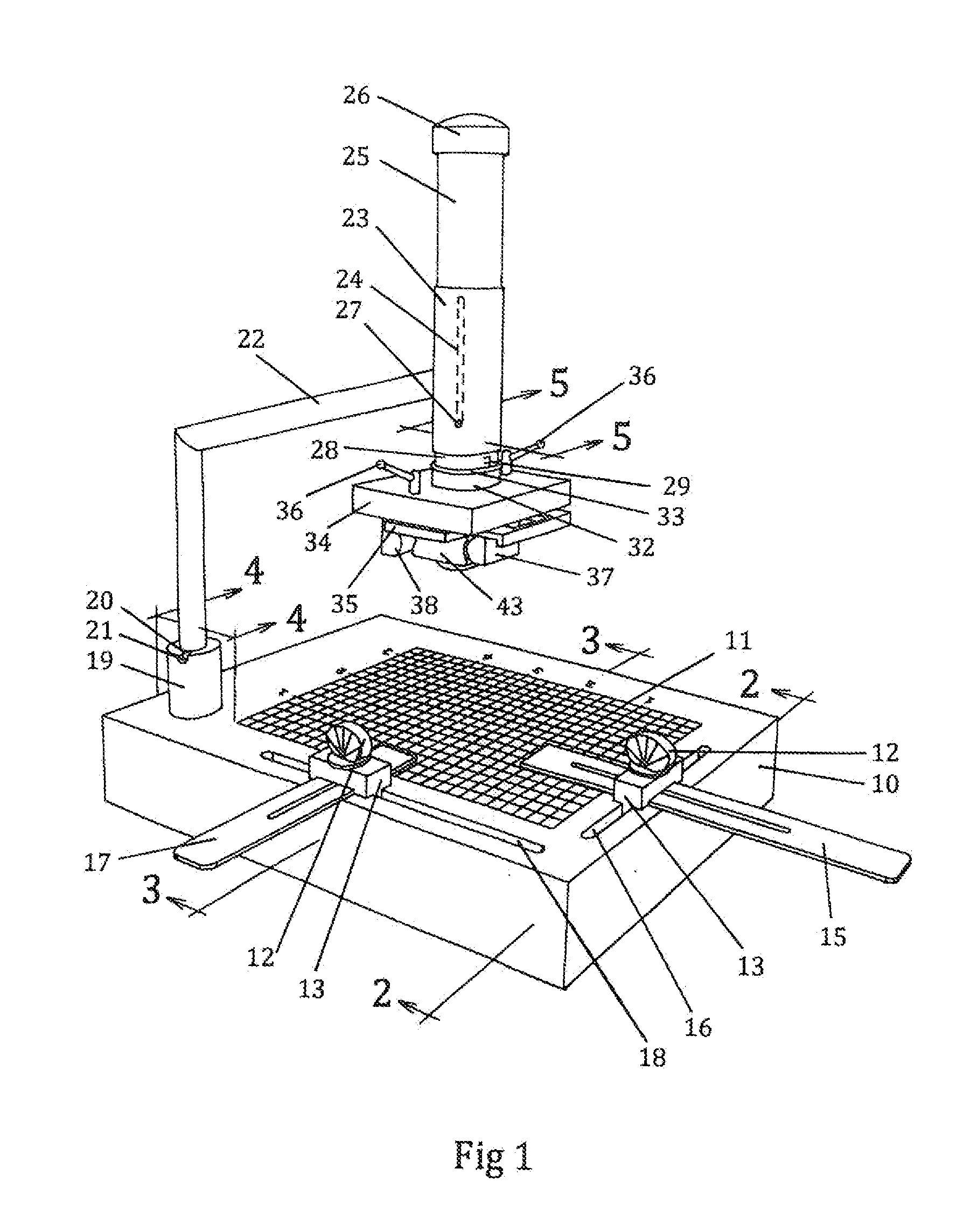
[0017]Referring to the perspective view FIG. 1, a preferred embodiment of my invention as comprising of a flat bed 10 adapted to receive and support one sheet of paper stock, or one envelope, or one blank form, or other medium upon which the printed impression is to be made on by means of paper stock alignment and securing it to bed 10, a plunger 25 by means to make the impression, and means to apply ink to stamp 43.

[0018]To facilitate accurate positioning of the sheet of paper stock, imprinted on the upper hard smooth surface of the bed 10 are appropriate grid lines 11. Said grid lines 11, commencing at four centimeter from bed 10 edge with interval of one-millimeter and parallel to vertical T-slot 16 and horizontal T-slot 18. Numerical graduation index are imprinted on bed 10 surface, reading horizontally left to right and vertically top to bottom.

[0019]Referring to FIG. 1, this embodiment requires two of slider 13, which are constructive identically; hence, one is used for longit...


PUM


Abstract

This apparatus is small, compact, and light-weight, relatively inexpensive in terms of manufacturing cost, and will substantially improve the quality of a stamped image, also used for repetitive printing on individual sheets of card stock or any flat printable surface, in the same pre-determined location, set be the user, which provides maximum flexibility in arrangement and adjustment to permit the apparatus to be used with various sizes of stamps, and various types of card stock and to be used to make a consistent inked impression at virtually any location on selected card stock.

Description

BACKGROUNDPrior Art[0001]Handheld stamps have been used for years to imprint words and images onto paper and have become the mainstay of many greeting card creators. Generally, stamping comprises of three-step process: first, the application of ink via an ink pad or roller to the stamp. Second, the positioning of the stamp in the general area chosen by creator and third, pressing the inked stamp firmly onto paper or specific medium.[0002]The transfer process generally provides an acceptable image with relatively modest applied pressure. However, several problems are encountered as complexity or size of the transfer image and location of the stamp onto the paper surface. Amongst these problems are ink coverage that may be less-than-complete, resulting in a stamped image that is also incomplete or with varied ink density. Mainly, this issue is attributed to ink pad distribution inconsistencies caused by ink roller unevenness (pressure or ink coverage), or a creator's own inability to ...

Claims


Application Information

Patent Timeline
IPC IPC(8): B41K3/00
CPCB41K3/04B41K3/62B41K3/56
Inventor KONIK, HENRY STEPHEN
Owner KONIK HENRY STEPHEN
Learn More